Static diffusion cell for diffusion sampling systems

a technology of diffusion sampling and cells, applied in the field of static diffusion cells, can solve the problems of inaccurate experimental data, variable or inaccurate calculation of cell volume, and difficult cell set-up, handling and cleaning

Active Publication Date: 2005-01-27
ALZA CORP
View PDF3 Cites 9 Cited by
  • Summary
  • Abstract
  • Description
  • Claims
  • Application Information

AI Technical Summary

Benefits of technology

[0010] In one aspect, the present invention is directed to a new design for a diffusion cell that can be used in conjunction with automated or manual sampling systems. In particular, the present invention provides a diffusion cell that integrates a diffusion chamber, sampling chamber, and bubble trap into a single receptor compartment. The cell design of the present invention allows for a diffusion cell that is completely free of tubing.

Problems solved by technology

However, applicants are presently aware of only two commercial systems that provide both static diffusion cells and automated sampling.
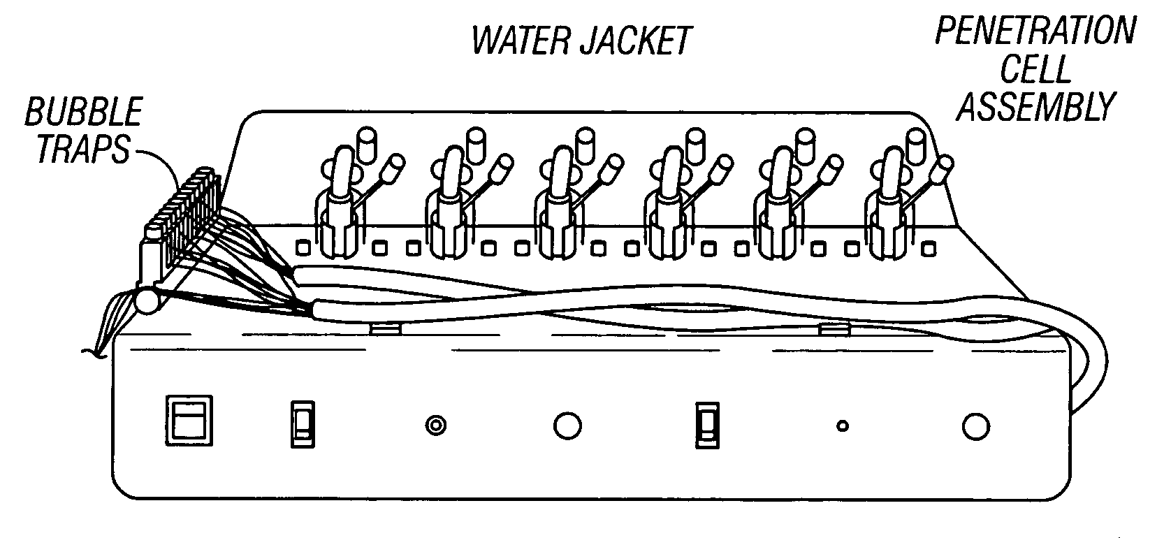
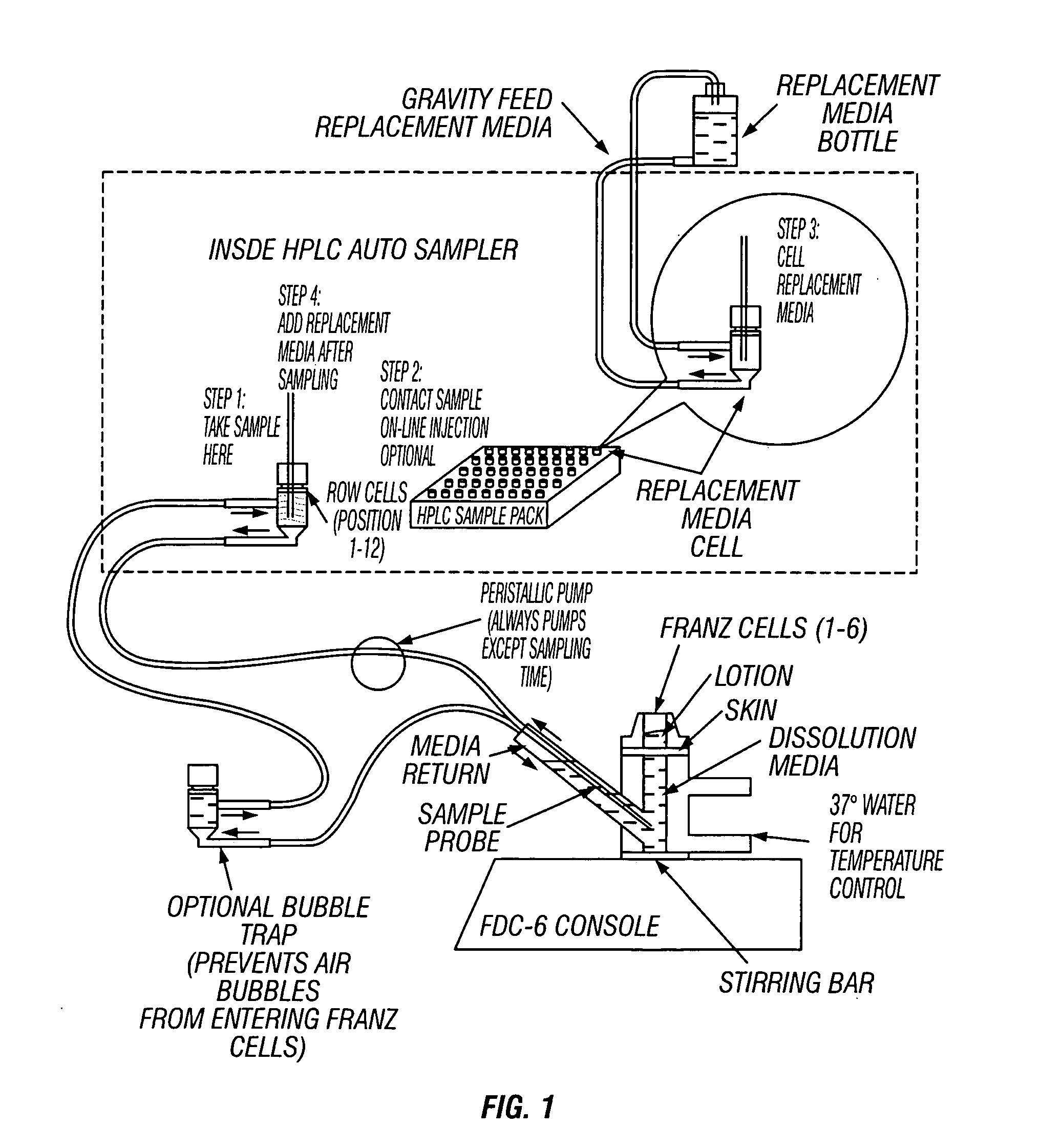
Although, the diffusion systems available from Hanson Research and Logan Instruments exhibit differences in design, the systems available from both companies includes a large amount of small diameter tubing and pumps (peristaltic or syringe) that move fluids through multiple compartments within the systems.
The designs of the systems described above can make cell set-up, handling, and cleaning difficult and can lead to inaccurate experimental data.
In particular, the relatively extensive use of tubing in the systems available from Logan Instruments Corp. and Hanson Research Corp. introduces several potential problems.
For example, the tubing can clog or leak, and the use of tubing can result in variable or inaccurate calculations of cell volume.
Perhaps even more problematic is binding of media constituents, such as the material to be assayed, to the tubing or leaching of chemicals from the tubing into the receptor medium.
Accumulation of air bubbles under the diffusion membrane causes a reduction in the area of the diffusion membrane in contact with the receptor medium, thereby reducing the effective diffusion area.
Such a reduction in diffusion area can, in turn, result in inaccurate experimental data.
However, removing air bubbles from the systems available from Logan Instruments Corp. and Hanson Research Corp. system is tedious at set-up and very difficult or even unattainable once a diffusion experiment has started.
Accordingly, when these systems are used, they typically require supervision to ensure that air bubbles do not accumulate under the diffusion membrane, which supervision defeats, at least in part, the purpose of having an automated sampling process.

Method used


Image

  • Static diffusion cell for diffusion sampling systems
  • Static diffusion cell for diffusion sampling systems
  • Static diffusion cell for diffusion sampling systems

Examples


first embodiment

[0029] the diffusion cell of the present invention is illustrated in FIG. 3. The diffusion cell of the present invention includes a single-chamber receptor compartment, a donor compartment, a diffusion membrane, and a sampling arm. As can be seen in FIG. 3, the diffusion membrane is positioned over the first outlet and once the diffusion cell is assembled, a top surface of the diffusion membrane forms at least a portion of the bottom surface of the donor compartment, and a bottom surface of the diffusion membrane forms at least a portion of the top surface of the receptor compartment. The diffusion membrane used in a diffusion cell according to the present invention may be any natural or synthetic material suitable for application in a diffusion cell. Natural membranes useful in a diffusion cell according to the present invention include, but are not limited to, skin, mucosal membranes, cornea, and epithelial membranes (e.g., intestinal, colonic, or nasal epithelial membranes). In a...


PUM

PropertyMeasurementUnit
volumeaaaaaaaaaa
diameteraaaaaaaaaa
volumesaaaaaaaaaa

Abstract

A new design for a static diffusion cell for use in a diffusion sampling apparatus to be used in conjunction with automated or manual sampling is disclosed. The diffusion cell of present invention provides to an improved and efficient diffusion assay system.

Description

CROSS-REFERENCE TO RELATED APPLICATION [0001] Pursuant to the provisions of 35 U.S.C. § 119(e), this application claims the benefit of the filing date of provisional patent application Ser. No. 60 / 458,905, filed Mar. 28, 2003, for “Static Diffusion Cell for Diffusion Sampling Systems.”BACKGROUND OF THE INVENTION [0002] 1. Field of the Invention [0003] The present invention relates to static diffusion cells useful in automated and manual diffusion sampling systems as well as assay methods that utilize diffusion sampling systems that include one or more diffusion cells according to the present invention. In particular, the present invention provides a static diffusion cell that includes a single chambered receptor compartment, which design reduces or eliminates the disadvantages associated with diffusion cells having multi-chambered receptor compartments and allows for improved sampling systems and assay methods. [0004] 2. Description of the Related Art [0005] In vitro membrane diffus...

Claims


Application Information

Patent Timeline
Patent Type & Authority Applications(United States)
IPC IPC(8): B01L99/00G01N1/20G01N1/34G01N13/00G01N13/04
CPCG01N1/2035G01N13/00G01N2013/003G01N2001/4016G01N13/04
Inventor YANG, HUAIMBERT, DELPHINE CAROLINE
Owner ALZA CORP
Why Eureka
Try Eureka