Discharge igniter for a waveguide CO2 laser

a co2 laser and ignition device technology, applied in lasers, laser details, active medium materials, etc., can solve the problems of increasing the complexity and cost of electronic circuitry, and the addition of circuitry in the rf power supply for generating the higher voltage ignition rf pulses,

Active Publication Date: 2005-01-27
COHERENT INC
View PDF3 Cites 8 Cited by
  • Summary
  • Abstract
  • Description
  • Claims
  • Application Information

AI Technical Summary

Benefits of technology

[0006] In one preferred embodiment, an igniter electrode is provided which is located in a blind hole aligned with the lateral extension. The spacing between the electrodes used to energize the gas in the waveguide channel is larger than the spa

Problems solved by technology

Either of these methods can require one or more power supplies involving electronic circuitry that is more complicated and expensive than would be required simply to provide that volt

Method used


Image

  • Discharge igniter for a waveguide CO2 laser
  • Discharge igniter for a waveguide CO2 laser
  • Discharge igniter for a waveguide CO2 laser

Examples


Embodiment Construction

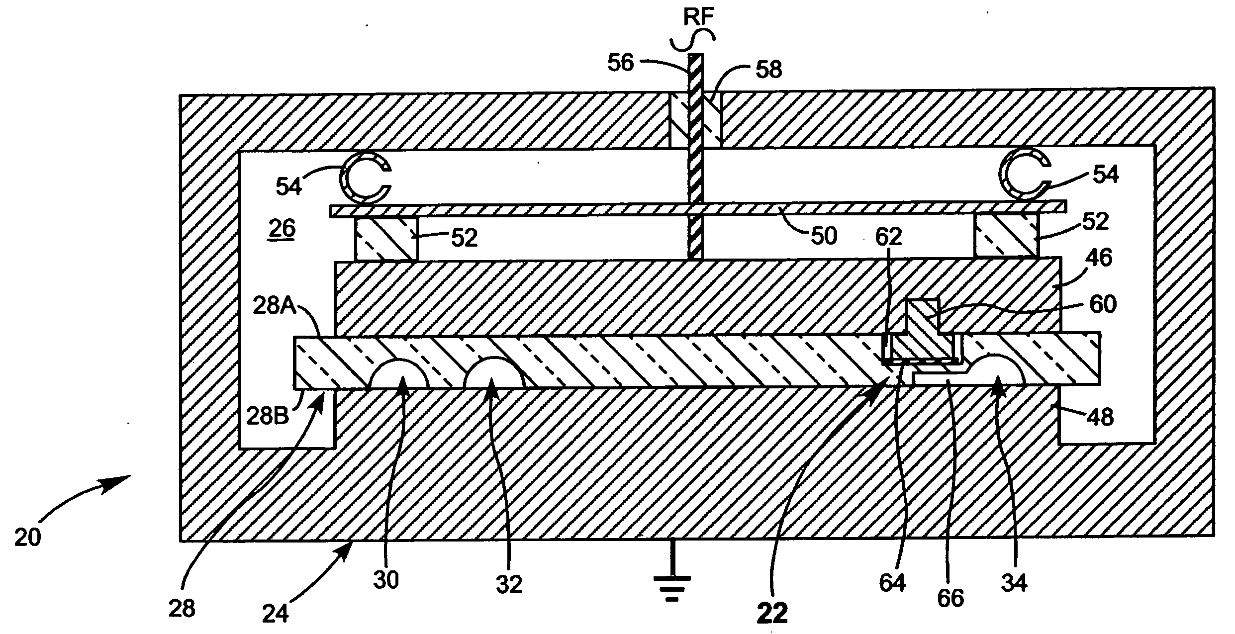
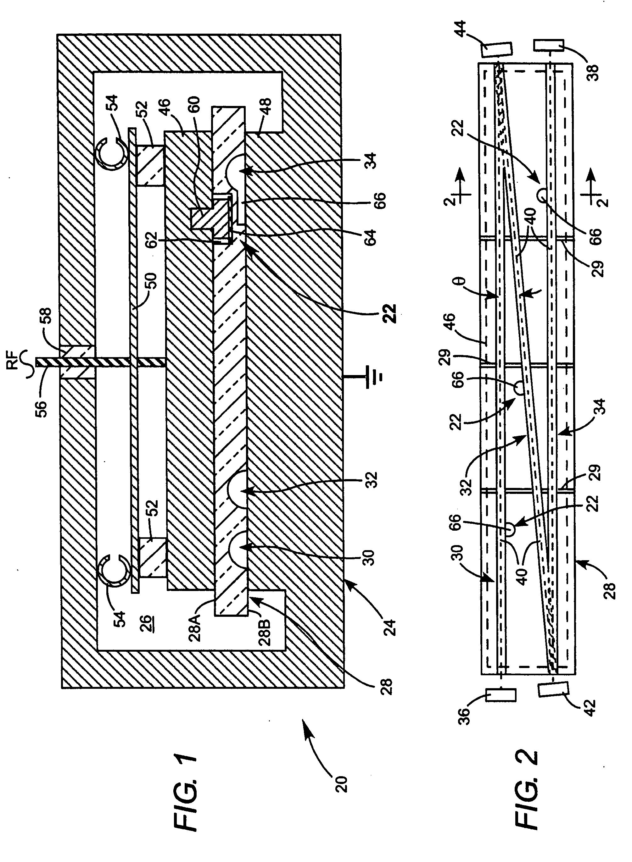
[0013] Referring now to the drawings, wherein like features include like reference numerals, FIG. 1 and FIG. 2 schematically illustrate one example of a folded-waveguide CO2 laser 20 including three discharge igniter arrangements 22 in accordance with the present invention. Only one of the igniter arrangements is visible in FIG. 1. Laser 20 includes a gas container 24 enclosing a lasing gas 26, here CO2. An elongated ceramic slab or block 28 includes three waveguide channels 30, 32, and 34, with adjacent ones thereof inclined at an angle θ to each other. The waveguide channels are indicated here as having a semicircular cross-section. The channels however, may have another cross-section shape, such as square, rectangular, or square or rectangular with rounded corners. Preferably, one igniter arrangement 22 is provided for each channel. Pressure relief slots 29 extend across the ceramic block providing fluid (gaseous) communication between the waveguide channels. Slots 29, serve, int...


PUM


Abstract

A waveguide gas laser includes an enclosure filled with a lasing gas. A ceramic block is provided with one or more waveguide channels. At least one of the waveguide channels includes an open region which is in fluid communication with a waveguide channel. Lasing gas in the enclosure fills the waveguide channels and the lateral extension. An electric field is applied across the lateral extension of the waveguide channel while simultaneously applying a smaller electric field across the waveguide channel. The electric field across the lateral extension ignites a discharge in the lateral extension that spreads into the lasing gas in the waveguide channel. The electric field across the waveguide channel is sufficient to sustain the discharge in the lasing in the waveguide channel.

Description

TECHNICAL FIELD OF THE INVENTION [0001] The present invention relates generally to gas lasers. The invention relates in particular to gas discharge ignition devices for carbon dioxide (CO2) lasers. DISCUSSION OF BACKGROUND ART [0002] In a CO2 laser, a discharge is maintained in a gaseous gain medium including CO2. The discharge may be maintained by applying either a radio frequency (RF) or a continuous (DC) high voltage to the gain medium. Prior CO2 lasers include a laser type generally referred to as a folded-waveguide laser. In a folded-waveguide laser, a ceramic block includes a plurality of waveguide channels arranged at an angle to each other to form the folded waveguide. The gaseous gain medium fills the waveguide and the discharge is maintained by applying the high voltage across parallel electrodes on either side of the block. A laser resonator including two end mirrors and one or more folding mirrors has a folded-resonator axis extending through the folded waveguide. Exampl...

Claims


Application Information

Patent Timeline
IPC IPC(8): H01S3/03H01S3/22H01S3/223
CPCH01S3/0315H01S3/076H01S3/2232
Inventor KENNEDY, JOHNLAUGHMAN, LANNYDEMARIA, ANTHONYSTRAAYER, RONALD
Owner COHERENT INC
Why Eureka
Try Eureka