
In-situ combustion combustion-supporting ignition method

A technology of burning oil layers and oil layers, which is applied in the direction of earthwork drilling, production fluid, wellbore/well components, etc. It can solve the problems of long ignition time and easy gas channeling in heavy oil reservoirs, so as to facilitate ignition and improve ignition effect, the effect of reducing air channeling

Active Publication Date: 2015-03-25
PETROCHINA CO LTD
View PDF5 Cites 32 Cited by
  • Summary
  • Abstract
  • Description
  • Claims
  • Application Information

AI Technical Summary

Problems solved by technology

[0006] The present invention provides a combustion-supporting ignition method for burning oil layers to at least solve the problem in the prior art that the ignition time for secondary development of heavy oil reservoirs is long and gas channeling is easily caused

Method used


Image

  • In-situ combustion combustion-supporting ignition method
  • In-situ combustion combustion-supporting ignition method
  • In-situ combustion combustion-supporting ignition method

Examples


Embodiment Construction

[0021] The following describes the technical solutions in the embodiments of the present invention clearly and completely with reference to the accompanying drawings in the embodiments of the present invention. Obviously, the described embodiments are only a part of the embodiments of the present invention, rather than all the embodiments. Based on the embodiments of the present invention, all other embodiments obtained by those of ordinary skill in the art without creative work shall fall within the protection scope of the present invention.

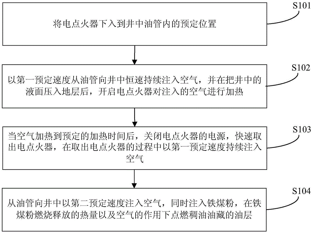
[0022] The embodiment of the present invention provides a combustion-supporting ignition method of a fired oil layer, figure 1 It is a flow chart of the method for combustion-supporting ignition of a fire-burning oil layer in an embodiment of the present invention, such as figure 1 As shown, the method includes the following steps:

[0023] Step S101, lower the electric igniter to a predetermined position in the oil pipe in the well. Speci...


PUM


Abstract

The invention discloses an in-situ combustion combustion-supporting ignition method. The method comprises the steps that an electric igniter is tripped in the preset position in an oil tube in a well; air is continuously injected into the well from the oil tube at a first preset speed, and after a liquid level in the well is pressed into a stratum, the electric igniter is started to heat the injected air; after the air is heated by the preset heating time, a power source of the electric igniter is turned off, the electric igniter is taken out, and the air is continuously injected at the first preset speed in the process of taking out the electric igniter; air is injected into the well from the oil tube at a second preset speed, meanwhile, iron pulverized coal is injected, and an oil layer of a heavy oil reservoir is ignited under the action of heat released by combustion of the iron pulverized coal and the air. Through the electric igniter, the oil layer is preheated, and water of near bore zones is reduced. The iron pulverized coal has the functions of profile correction and channeling blocking, combustion products are stored in holes, a gas entry profile continues to be adjusted, ignition is facilitated better, gas channeling is reduced, and meanwhile fast ignition is achieved.

Description

Technical field [0001] The invention relates to the field of heavy oil reservoir development, in particular to a combustion-supporting ignition method for a fired oil layer. Background technique [0002] Burning oil layer is an effective technology to improve oil recovery, and it can be applied under more complicated and harsh formation conditions than steam flooding. Ignition is the most important step. Only successful ignition can ensure the continued implementation of the fire drive. If the first ignition fails, the difficulty of the second ignition will be greatly increased. For heavy oil reservoirs, the current ignition process mainly includes the following three types: steam injection spontaneous ignition, steam injection + chemical agent ignition and mobile electric ignition. [0003] At present, most of the reservoirs converted from heavy oil development are those that have undergone multiple rounds of steam stimulation. The water saturation near the well is high, and due ...

Claims


Application Information

Patent Timeline
Patent Type & Authority Applications(China)
IPC IPC(8): E21B43/243
CPCE21B43/243
Inventor 张洪君于晓聪周立国曲绍刚刘锦阚长宾汪小平崔冠麟
Owner PETROCHINA CO LTD
Learn More