
Method and system for of compensating for data storage disc stack imbalance during disc drive assembly

a technology of disc drive and stack imbalance, which is applied in the field of real-time compensation of data storage disc drive imbalance, can solve the problems of structural vibration and undesirable noise, poor process capability of current disc drive assembly process, and large design changes in the direction of data recording, instruments,

Inactive Publication Date: 2005-01-27
SEAGATE TECH LLC
View PDF13 Cites 5 Cited by
  • Summary
  • Abstract
  • Description
  • Claims
  • Application Information

AI Technical Summary

Benefits of technology

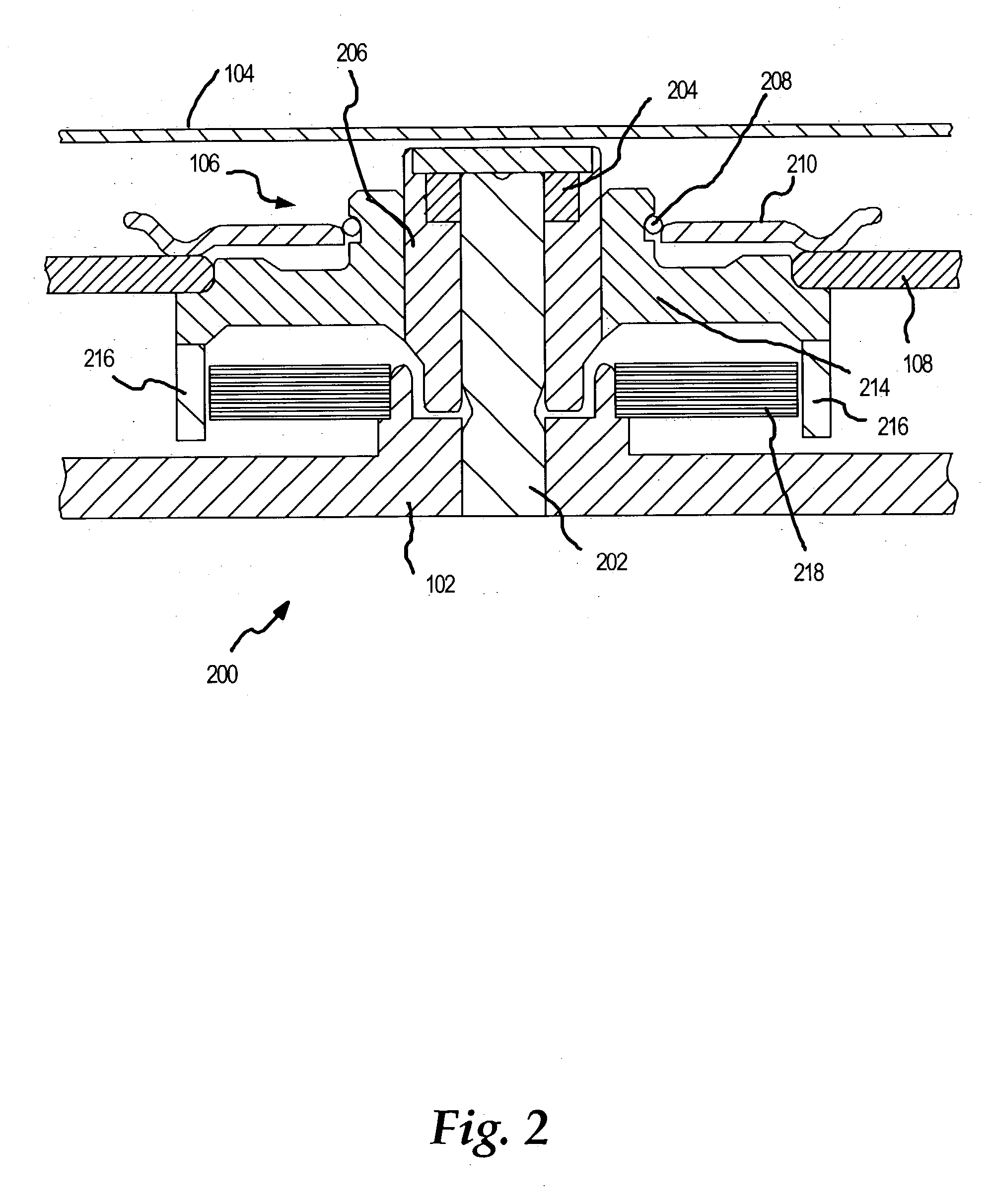
Against this backdrop embodiments of the present invention have been developed. One embodiment is a method of compensating for imbalance in data storage disc stack processing during assembly of the data storage device. The method incorporates an optical measurement system downstream of the disc clamp installation operation. The introduction of a real-time optical measurement system into the assembly line has numerous strategic advantages. The system measures multiple parameters of a most recent set N of incoming disc-stacks produced on the assembly line, where N is a suitable sample size, such as 30 disc stacks. The measured parameters include disc clamp Offset, clamp offset angle, ring outer diameter, ring offset, and ring offset angle, where the disc clamp may be installed with a spring expansion ring designed to center the clamp with respect to the axial centerline of the drive motor. The optical capabilities of the system provide quantitative measurement of the install conditions for the clamp and other components, which permits optimization of the components and machine settings. For instance, the optical system may inspect the ring closure condition to avoid reliability issues due to slippage of the disc media.
During assembly of the next disc stack, the clamp installation station receives and installs the clamp configuration type that compensates for imbalance in that disc stack according to the offset trend. The clamp offset and clamp offset angle of this next assembled disc stack are then measured for use in the next moving average calculation for the most recent N disc stacks produced on the assembly line. This process results in a significantly better balancing process capability and improved product quality throughput. The optical measurement system also recognizes supplier codes printed on the components and can track assembly data such that the calculated averages may be correlated with the machine that installed the clamp and the supplier of the clamp: This enables optimization and comparison of installation equipment settings and component parts.

Problems solved by technology

High imbalance of the disc stack may lead to structural vibration and undesirable noise, both of which are unacceptable in consumer products such as games-boxes and audio-video products.
The condition of the machine that is used to assemble the disc clamp onto the stack, the centering of the ring, as well as the clamp shape are all factors that can contribute to the overall stack imbalance.
With an industry standard of 50 mg-cm for static imbalance, and with the incoming drive components being at optimum condition, current processes for the assembly of disc drives still have poor process capability.
However, corrective actions typically involve major design changes and added cost such as Active Balancing which requires a design change and the addition of counter-balance weights.
These solutions also require extra manufacturing floor space and labor to perform the corrective balancing.

Method used


Image

  • Method and system for of compensating for data storage disc stack imbalance during disc drive assembly
  • Method and system for of compensating for data storage disc stack imbalance during disc drive assembly
  • Method and system for of compensating for data storage disc stack imbalance during disc drive assembly

Examples


Embodiment Construction

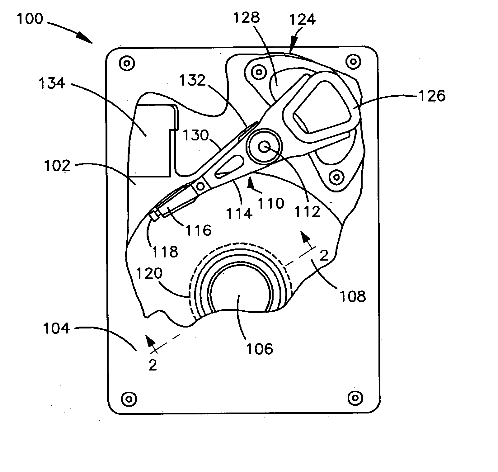
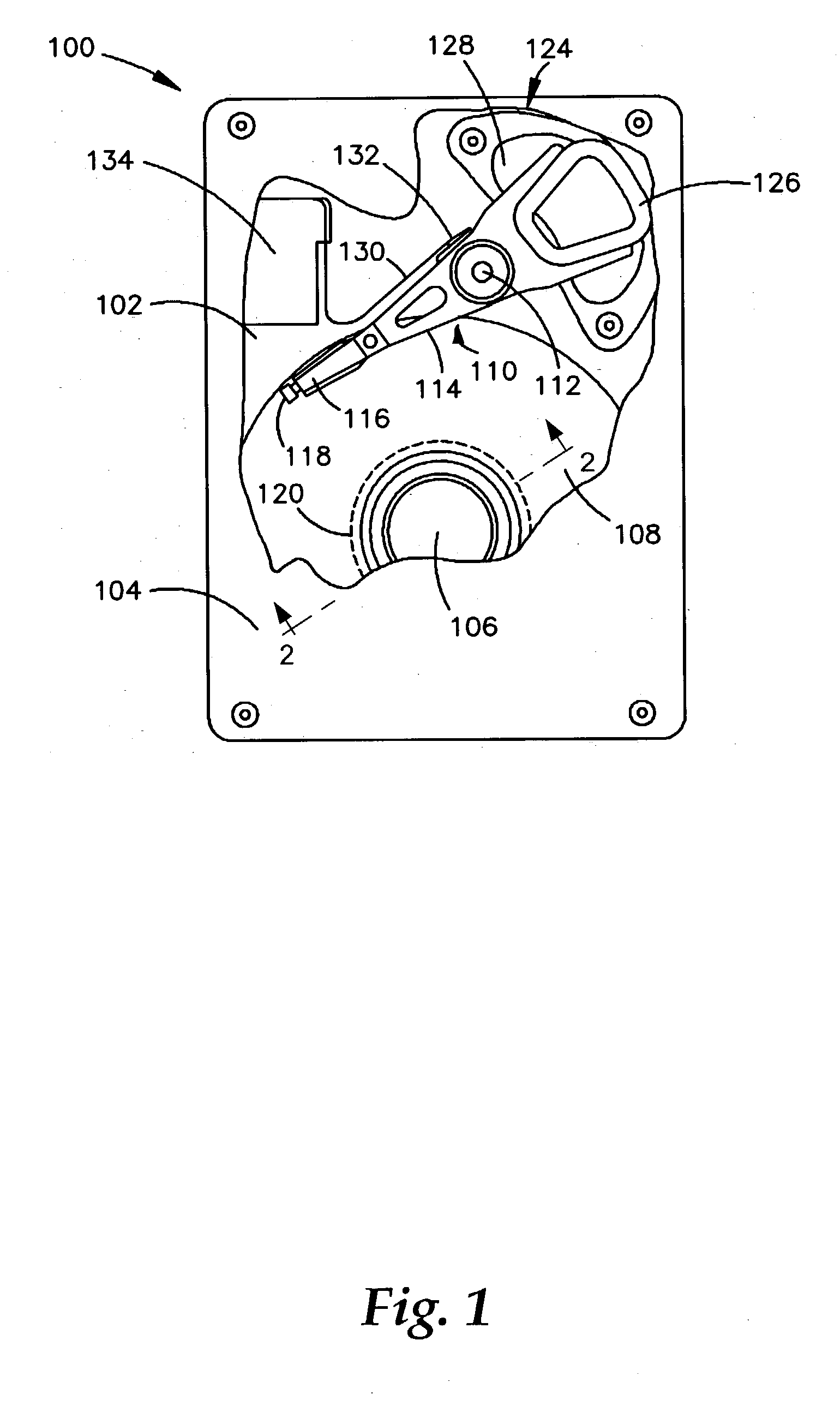
A disc drive 100 constructed in accordance with a preferred embodiment of the present invention is shown in FIG. 1. The disc drive 100 includes a base 102 to which various components of the disc drive 100 are mounted. A top cover 104, shown partially cut away, cooperates with the base 102 to form an internal, sealed environment for the disc drive in a conventional manner. The components include a spindle motor 106 which rotates one or more discs 108 at a constant high speed. Information is written to and read from tracks on the discs 108 through the use of an actuator assembly 110, which rotates during a seek operation about a bearing shaft assembly 112 positioned adjacent the discs 108. The actuator assembly 110 includes a plurality of actuator arms 114 which extend towards the discs 108, with one or more flexures 116 extending from each of the actuator arms 114. Mounted at the distal end of each of the flexures 116 is a head 118 which includes a fluid bearing slider enabling the h...


PUM

PropertyMeasurementUnit
clamp offset angleaaaaaaaaaa
anglesaaaaaaaaaa
anglesaaaaaaaaaa

Abstract

A method and system of compensating for imbalance in a data storage disc stack during assembly of the data storage device. The method introduces an optical measurement system downstream of the disc clamp installation operation. The system measures multiple parameters of a most recent N incoming disc-stacks produced on the assembly line, where N is a suitable sample size, such as 30 disc stacks. The measured parameters can comprise disc clamp offset, clamp offset angle, and ring outer diameter. After measuring parameters for a suitable sample size N, the optical system calculates a dynamic or moving average of the most recent N disc stack component offsets and / or offset angles. The calculated averages are then utilized to determine a component configuration type that will compensate for the disc stack imbalance according to the offset trend. The system then feeds back the clamp configuration type to a clamp installation operation where the configuration type is installed during assembly of the next disc stack.

Description

FIELD OF THE INVENTION This application relates generally to data storage disc drive manufacturing and assembly and more particularly to real time compensation for data storage disc drive imbalance. BACKGROUND OF THE INVENTION The static imbalance of data storage disc stack assemblies, usually expressed in milligram-centimetres (“mg-cm”), has recently become a critical performance parameter in disc drive design. This is primarily due to the increasing demand for precision performance in the consumer data storage product market. High imbalance of the disc stack may lead to structural vibration and undesirable noise, both of which are unacceptable in consumer products such as games-boxes and audio-video products. Furthermore, the industry standard specification for drive level imbalance has been reduced from an industry standard, 70 mg-cm to the current state of the aft, 50 mg-cm. The major contributors to the disc stack imbalance of a typical disc drive include disc clamp offset, ...

Claims


Application Information

Patent Timeline
Patent Type & Authority Applications(United States)
IPC IPC(8): G01B11/14G11B5/09G11B17/028G11B17/038
CPCG11B17/028G11B17/038G11B17/0287
Inventor SU, GUO CHUNCHEN, MING HUING, HWA LIANGCHENG, TERENCE CHEEKWONG
Owner SEAGATE TECH LLC
Learn More