
Device for delivering printed products and machine and method for processing printed products

Inactive Publication Date: 2005-05-19
KOENIG & BAUER AG
View PDF4 Cites 0 Cited by
  • Summary
  • Abstract
  • Description
  • Claims
  • Application Information

AI Technical Summary

Benefits of technology

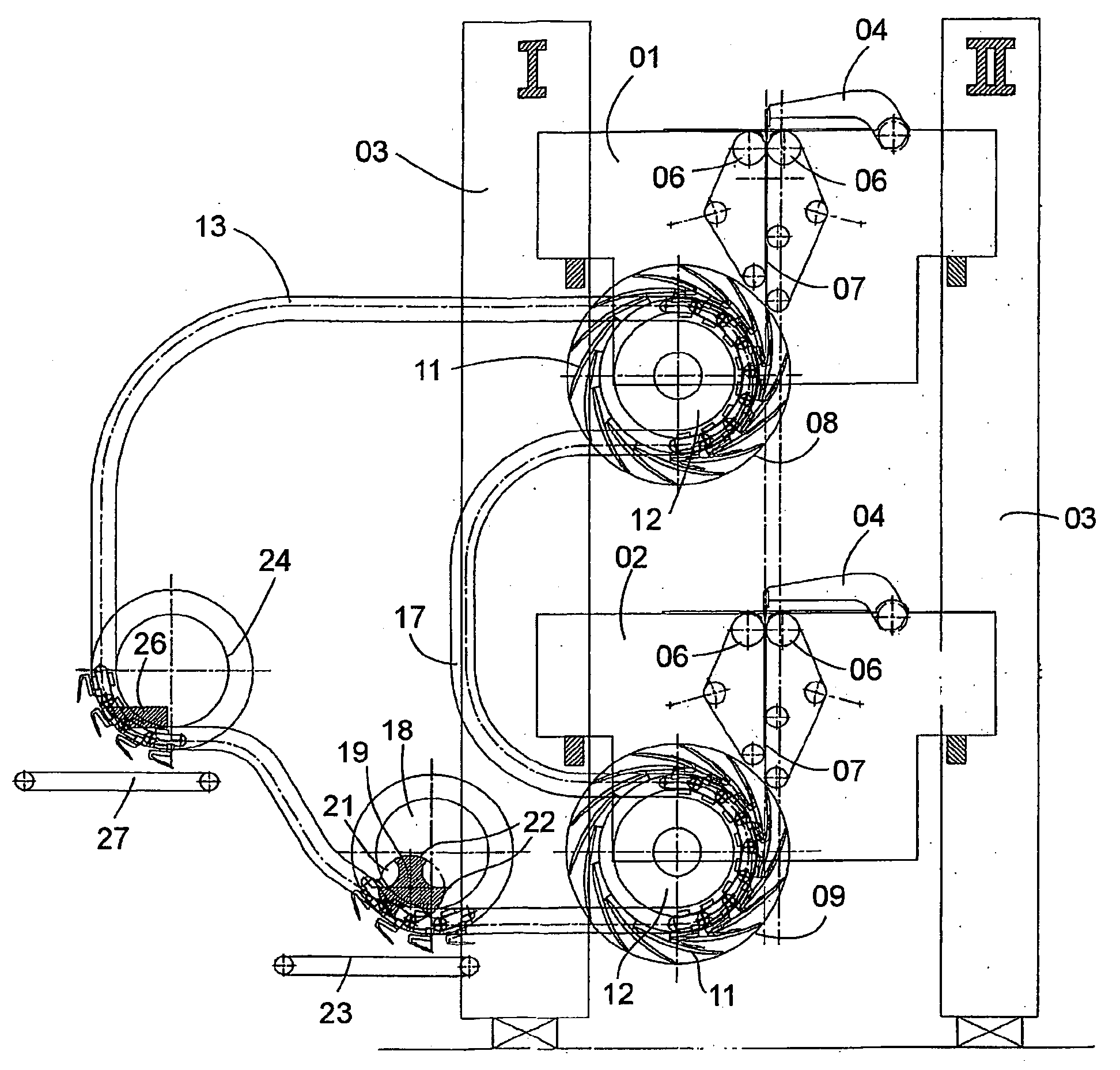
[0009] In the device in accordance with the present invention, the joining of the product streams takes place at the second paddle wheel, at which time and location the grippers of the gripper chain, which had remained empty during the passage of the gripper chain around the first paddle wheel, are now equipped or provided with products of the second product stream. Since the two paddle wheels can be placed substantially at any arbitrary locations along the path of travel of the gripper chain, there is no necessity to place conveyor belt arrangements, for delivering the two product streams, so closely together that they can introduce the products into the same paddle wheel. This elimination of such side constraints simplifies the construction of the device or of an apparatus with which it is employed. It also permits the optimization of the placement of its components, for example in view of modularity, in the use of as many uniform components as possible, for easy accessibility for maintenance purposes, and the like.
[0014] Since the paddle wheels can be arranged at substantially any arbitrary position along the gripper chain, the placement of the folding devices is subjected to only a few side constraints. This makes possible the use of completely identical folding devices or folding arrangements and thus accomplishes the reduction of the construction costs of the machine. It can also accomplish, among other things, the arrangement of the folding devices on top of each other in order to provide a machine having little space requirements, and in which both folding devices are easily accessible, in the same way, for maintenance purposes.

Problems solved by technology

With this known device, this desired product deposition is only possible if the printed products have already been inserted into the paddles of the paddle wheel in an alternating manner.

Method used


Image

  • Device for delivering printed products and machine and method for processing printed products
  • Device for delivering printed products and machine and method for processing printed products
  • Device for delivering printed products and machine and method for processing printed products

Examples


Embodiment Construction

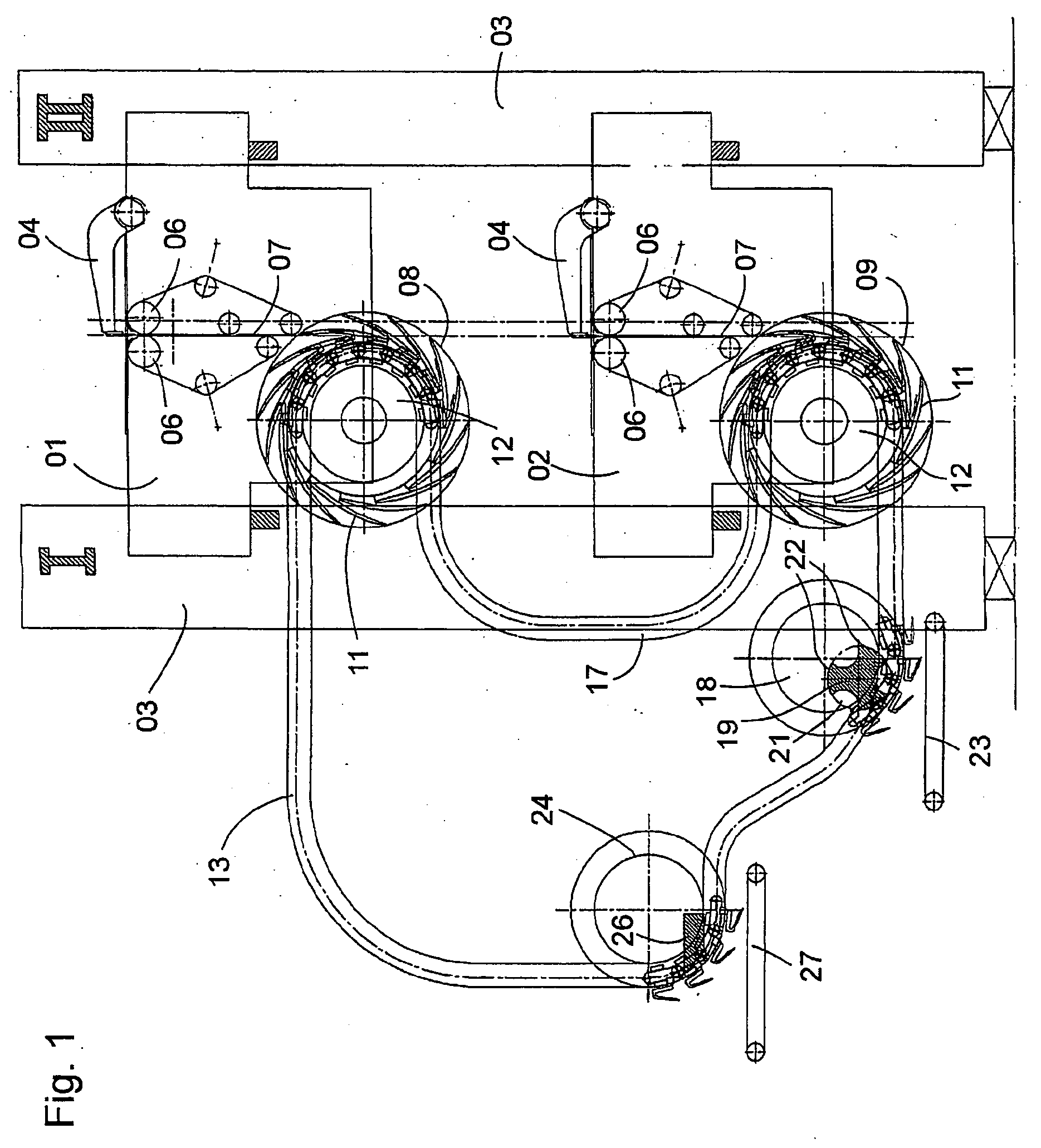
[0022] Referring initially to FIG. 1, there may be seen a side elevation view of a device for delivering printed products in accordance with the present invention,. The machine represented in FIG. 1 is comprised of an upper longitudinal folding device 01 and of a lower longitudinal folding device 02, which two folding devices 01, 02 have been placed on top of each other between supports 03 of a lateral frame. A pivotable folding blade 04 of each of the two longitudinal folding devices 01, 02 is used for introducing a respective presented signature between folding rollers 06 of the associated folding device and to form in this way, a longitudinal fold in each of the signatures. The now folded signatures are clamped between two facing endless belts of a belt guide device 07, which belt guide device 07 starts at the associated folding rollers 06. These signatures are then guided downward to one of an upper paddle wheel or a lower paddle wheel 08 or 09 and fall into their paddles or poc...


PUM

PropertyMeasurementUnit
Structureaaaaaaaaaa

Abstract

A device that is usable for delivering printed products includes two bucket or paddle wheels that can rotate about two different axes of rotation. Each bucket or paddle wheel includes a plurality of scoop-type elements that can receive printed products from a first or a second product flow. A gripper chain is guided around the two different axes of rotation. Grippers are arranged on the gripper chain and can grip and printed products received in the scoop-type element to thereby remove the product from the scoop. At least one device that will open the grippers, for release of the printed products held by the grippers, is arranged along the path of travel of the gripper chain.

Description

CROSS-REFERENCE TO RELATED APPLICATIONS [0001] This patent application is the U.S. National Phase, under 35 U.S.C. 371, of PCT / DE03 / 00671, filed Feb. 28, 2003; published as WO 03 / 080489 A2 and A3 on Oct. 2, 2003 and claiming priority to DE 102 13 461.8, filed Mar. 26, 2002, the disclosures of which are expressly incorporated herein by reference.FIELD OF THE INVENTION [0002] The present invention is directed to a device for delivering printed products, as well as to a method for processing printed products. At least two paddle wheels, which receive products from two product streams, have those products removed by a single gripper chain. BACKGROUND OF THE INVENTION [0003] A device for delivering printed products is known from DE 196 42 130 C2. [0004] This device is comprised of a paddle wheel, into whose paddles or pockets printed products are inserted. A gripper chain, which is conducted around the rotary shaft of the paddle wheel, has a plurality of grippers for picking up a product...

Claims


Application Information

Patent Timeline
IPC IPC(8): B65H29/04B65H29/40B65H29/60B65H45/18
CPCB65H29/003B65H2402/546B65H29/60B65H45/18B65H2301/4454B65H2301/44712B65H2301/4473B65H2301/44765B65H2403/512B65H2405/58B65H29/40B65H2220/01B65H2220/02B65H2220/09B65H2402/54B65H2701/1924
Inventor RATZ, HOLGER
Owner KOENIG & BAUER AG
Learn More