Photoprinter

a technology of photoprinter and plate, which is applied in the field of photoprinter, can solve the problems of paper loss and failure, and achieve the effects of reducing manhour in assembly, freeing up a position, and facilitating assembly

Inactive Publication Date: 2005-01-27
FUNAI ELECTRIC CO LTD
View PDF0 Cites 0 Cited by
  • Summary
  • Abstract
  • Description
  • Claims
  • Application Information

AI Technical Summary

Benefits of technology

[0016] With such constitution, when the margin paper is cut by the cutting device, it is received from the opening at the upper portion of the box-shaped margin paper receiving device to accumulate successively. Also, by setting the turning device to turn the margin paper receiving device to a position, in which the opening of the margin paper receiving device is directed obliquely downward, or downward, the margin paper received in the margin paper receiving device can be ejected when the number of times counted by the counting device reaches a set value. Accordingly, a user can easily discard the margin paper. Also, with the photoprinter, the margin paper receiving device is not removed but turned to eject the margin paper, so that there is no fear that a user erroneously inserts a hand into the vicinity of the cutting device, whereby it is possible to prevent a user from getting hurt by the cutter device.
[0018] With such constitution, when the number of times counted by the counting device reaches a set value, the turning device is actuated to turn the margin paper receiving device whereby the margin paper received in the margin paper receiving device can be easily ejected. Also, with the photoprinter, the margin paper receiving device is not removed but the lid is opened to eject the margin paper, so that there is no fear that a user erroneously inserts a hand into the vicinity of the cutting device, whereby it is possible to prevent a user from getting hurt by the cutter device.
[0020] With such constitution, the fan is set to blow the wind inside the margin paper receiving device when the margin paper should be ejected from the margin paper receiving device, so that the wind from the fan can be made use of in order to eject the margin paper and the margin paper can be ejected from the margin paper receiving device in a short period of time. Accordingly, a user can form a picture in the photoprinter without caring about that timing, at which the margin paper accumulated in the photoprinter should be discarded.
[0022] With such constitution, the plurality of gaps are provided at least on the bottom surface of the margin paper receiving device, so that the fan can blow the wind inside the margin paper receiving device from the bottom surface thereof. Accordingly, freedom in a position, in which the fan is arranged, is increased, so that it is possible to install the fan in a position, in which assembly is easy, and to reduce manhour in assembling. Also, by arranging the fan in a position suited for ventilation in the photoprinter, the fan can serve for ejection of the margin paper and for ventilation in the photoprinter, which makes it possible to prevent an increase in cost.

Problems solved by technology

Therefore, the apparatus involves a problem that pieces of paper (margin paper) overflow the paper piece recovering device to cause lodgment of paper and failure.

Method used


Image

  • Photoprinter
  • Photoprinter
  • Photoprinter

Examples


Embodiment Construction

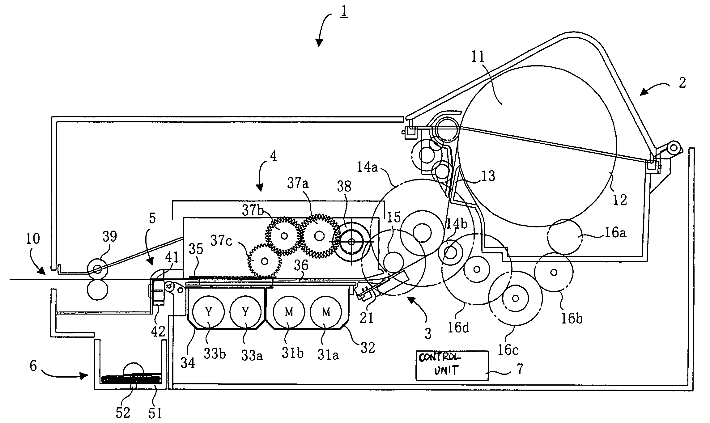
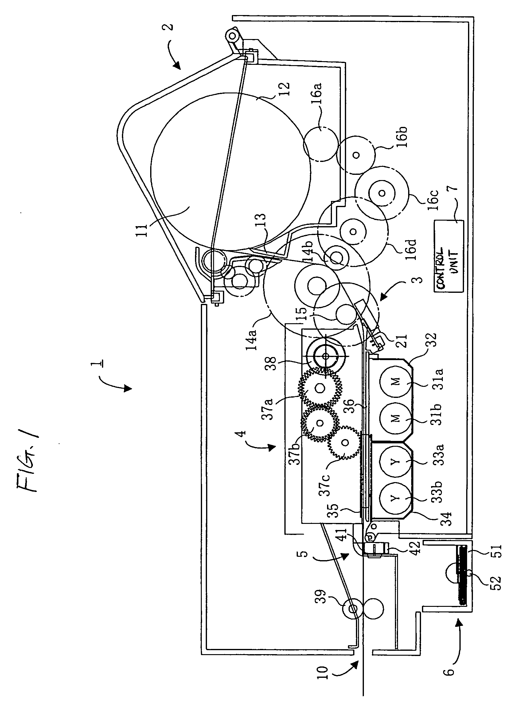
[0030]FIG. 1 is a front, perspective view schematically showing a constitution of a photoprinter according to an embodiment of the invention. In the following descriptions, a printer of the TA system (also called a thermo-autochrome system or a light fixing type direct thermal recording system) will be explained by way of example. Here, the TA system is one that forms a full color picture by repeating heating by a thermal head and fixing by irradiation of ultraviolet rays on a special purpose paper, which is called TA paper, and on which three thermal color development layers for color development of three primary colors of Y (yellow)•M (magenta)•C (cyanogen) are laminated.

[0031] As shown in FIG. 1, a photoprinter 1 includes a paper feeding section 2, a picture forming section 3, a fixing unit 4, a cutting section 5, a margin paper receiving section 6, and a control unit 7. The paper feeding section 2 includes a roll-paper holding member 12 that supports a roll paper 11 formed by w...


PUM


Abstract

When a margin paper constituting a margin between pictured formed sheets, on which pictures have been formed, is cut by a cutter, it is received in a casing. The number of times, in which cutting means cuts a number of sheets to avoid overflowing of the margin paper received in the casing, is beforehand set as a set value, and the number of times, in which the cutter cuts a roll paper, is counted. When a count value reaches the set value, a control unit turns the casing so that an upper opening of the casing is directed downward, and causes the margin paper in the casing to be ejected. When a predetermined period of time has elapsed, the casing is again turned to be returned to an original state. The number of times as counted is reset and counting is again performed.

Description

BACKGROUND OF THE INVENTION [0001] 1. Field of the Invention [0002] The present invention relates to a photoprinter provided with margin paper receiving device that receives a margin cut off from a continuous paper. [0003] 2. Description of the Related Art [0004] Photoprinters use a roll paper to be able to continuously print photographs having different sizes such as normal size, panorama size, etc. without replacing sheets. In photoprinters, when a picture is formed on a roll paper, that portion (a trailing end of a portion, on which the picture is formed), on which the picture is not formed, is in some cases exposed to light. Therefore, with conventional photoprinters, such portion (margin paper) exposed to light is cut / ejected and a portion (picture formed paper), on which a picture is formed, is cut / ejected. [0005] Conventional photoprinters include a container that recovers therein a margin paper. There has been proposed a photoprinter provided with a weight detector that dete...

Claims


Application Information

Patent Timeline
Patent Type & Authority Applications(United States)
IPC IPC(8): B41J11/70G03B29/00
CPCG03B29/00
Inventor YOSHIDA, YUICHIMAEDA, TAKASHI
Owner FUNAI ELECTRIC CO LTD
Why Eureka
Try Eureka