
Method and a system to dispense and detect fluorescent quantum dots

Inactive Publication Date: 2005-01-27
CALIFORNIA INST OF TECH
View PDF3 Cites 13 Cited by
  • Summary
  • Abstract
  • Description
  • Claims
  • Application Information

AI Technical Summary

Benefits of technology

The present invention combines fluorescent nano-particles (also known as quantum dots or QDs) and methods to dispense and detect them efficiently in a compact volume for a range of optical tagging applications ranging from security/identification, counterfeit, ultra-high density data storage, manufacturing assembly, military to civil remote sensing. According to one embodiment, micro-fluidic devices are used for mixing water-soluble fluorescent nano-particles in aqueous solutions to create a multi color fluorescent tag called a nano-optical tag. According to another embodiment, gratings are used for spreading the spectral components of the fluorescent signal leading to an improvement in optical data storage capacity over prior art methods. According to another embodime

Problems solved by technology

Technologies based on both bar-coding and RF have difficulties.
Bar-code tags have to be manually scanned one at a time, and RF tags are at times difficult to introduce due to such handicaps as high volume / low cost, high tagging throughput of small parts, large number of combinations, and use with optical discs such as CDs and DVDs causing interference with the laser.
Even though the primary benefit of RDIF tags over barcodes is their ease of use and reliability, RDIF tags cannot be placed on nano size objects or when a very high information density is required.
This characteristic could create a problem when different liquids are mixed to produce a homogeneous solution, especially organic liquids that tend to be sticky.

Method used


Image

  • Method and a system to dispense and detect fluorescent quantum dots
  • Method and a system to dispense and detect fluorescent quantum dots
  • Method and a system to dispense and detect fluorescent quantum dots

Examples


Embodiment Construction

The present invention relates to a technology that combines fluorescent QDs and methods to dispense and detect them for a range of optical tagging applications. In the following description, numerous specific details are set forth to provide a more thorough description of embodiments of the invention. It is apparent, however, to one skilled in the art, that the invention may be practiced without these specific details. In other instances, well known features have not been described in detail so as not to obscure the invention.

Basic Schematic

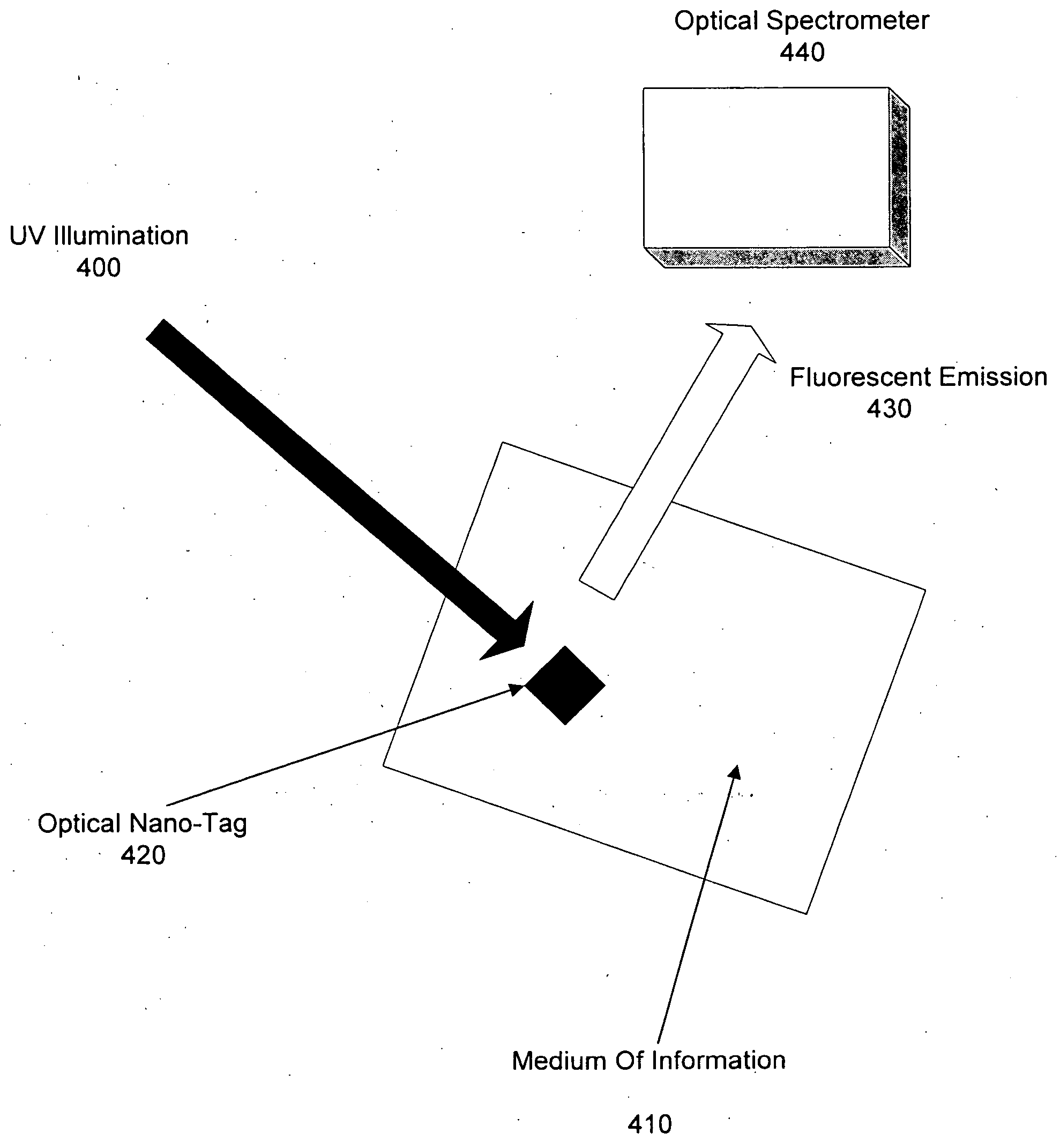
The basic schematic of the present technology is shown in FIG. 4. Optical tag 420 composed of many fluorescent QDs is disposed on the surface of medium 410 that needs protection. When UV illumination 400 is turned on, the optical tag 420 fluoresces. Optical spectrometer 440 analyzes the fluorescent emission 430 representing the passive fingerprint of the tag. According to one embodiment, medium 410 is made up of an embossed material. The emb...


PUM


Abstract

The invention combines fluorescent QDs and methods to dispense and detect them efficiently in a compact volume for a range of optical tagging applications. Micro-fluidic devices are used for mixing water-soluble fluorescent QDs in aqueous solutions to create a multi color fluorescent nano-optical tag, and gratings are used for spreading the spectral components of the fluorescent signal leading to an improvement in optical data storage capacity over prior art methods. The spectral signature of the tag is detected by a compact read-out head with a grating spectrometer. One way is to dispense the tag within the pits of a DVD or CD using an ink-jet nozzle and exciting them by a large range of wavelengths each shorter that the emission peak. The filters have a high immunity to prolonged exposure to high temperatures, and up to 41 infrared filters can be holographically recorded by spatial multiplexing of the substrate.

Description

BACKGROUND OF THE INVENTION 1. Field of the Invention The present invention relates to the field of image sensing devices and applications. More specifically, the present invention relates to a technology that combines fluorescent nano-particles (quantum dots) and methods to dispense and detect them for a range of optical tagging applications. Portions of the disclosure of this patent document contain material that is subject to copyright protection. The copyright owner has no objection to the facsimile reproduction by anyone of the patent document or the patent disclosure as it appears in the Patent and Trademark Office file or records, but otherwise reserves all rights whatsoever. 2. Background Art An increase in the awareness for security and fraud protection systems at many levels has created an influx in tagging applications in such fields as security / identification, counterfeit, ultra-high density data storage, manufacturing assembly, military, and civil remote sensing. P...

Claims


Application Information

Patent Timeline
IPC IPC(8): G01N21/64G06K7/10
CPCB82Y10/00B82Y20/00G01N2021/6421G01N2021/6417G01N21/643
Inventor PSALTIS, DEMETRIMOSER, CHRISTOPHE
Owner CALIFORNIA INST OF TECH
Learn More