Mobile, self-sufficient operating assembly for providing electrical energy

a technology of operating assembly and electrical energy, which is applied in the direction of electrical apparatus, dynamo-electric machines, control systems, etc., can solve the problems of increasing construction volume and weight, increasing the cost of electrical energy consumption, etc., to achieve the effect of improving the supply of electrical energy, increasing flexibility, and low power demand

Inactive Publication Date: 2005-01-20
EADS DEUT GMBH
View PDF12 Cites 9 Cited by
  • Summary
  • Abstract
  • Description
  • Claims
  • Application Information

AI Technical Summary

Benefits of technology

[0004] The more recent development of military power supply systems in the range from 1 to 60 Kw—even smaller units for the DC supply—attempt to provide reduction of weight and constructional volume, while saving fuel and increasing reliability. Here also, smaller aggregates form an independent transport unit or are installed in a space, the so-called technical area, which is separated from the working area of a container. An increased reliability (extension of the MTBF—Mean Time Between Failure—and reduction of the maintenance expenditures) is achieved by an ample dimensioning of all components and monitoring of the system-sensitive functions (temperatures, fuel supply and oil supply) by means of a corresponding modification of the COTS (Commercial Of The Shelf) products (stored-program control).
[0038] On the whole, the invention provides an aggregate by means of which a high reliability of the power supply can be achieved without significantly having to increase the construction volume and own weight.

Problems solved by technology

However, in the case of highly mobile systems, this is prevented by cost, an increased constructional volume and weight.
The high-priority energy supply is maintained, while the consuming devices with low priority can no longer be supplied.
Although a doubling of the nominal power of each generator (which at first glance seems possible because both internal-combustion engines are still available for the operation) is possible as a further embodiment of the invention, on the whole, it results only in a relatively inefficient improvement of the partial redundancy.

Method used


Image

  • Mobile, self-sufficient operating assembly for providing electrical energy
  • Mobile, self-sufficient operating assembly for providing electrical energy
  • Mobile, self-sufficient operating assembly for providing electrical energy

Examples


Embodiment Construction

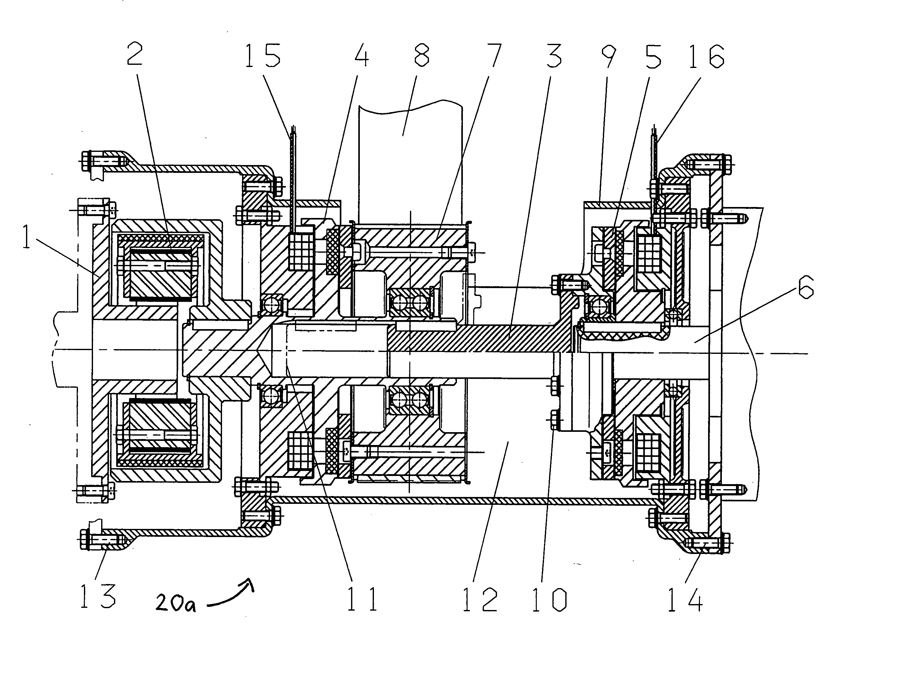
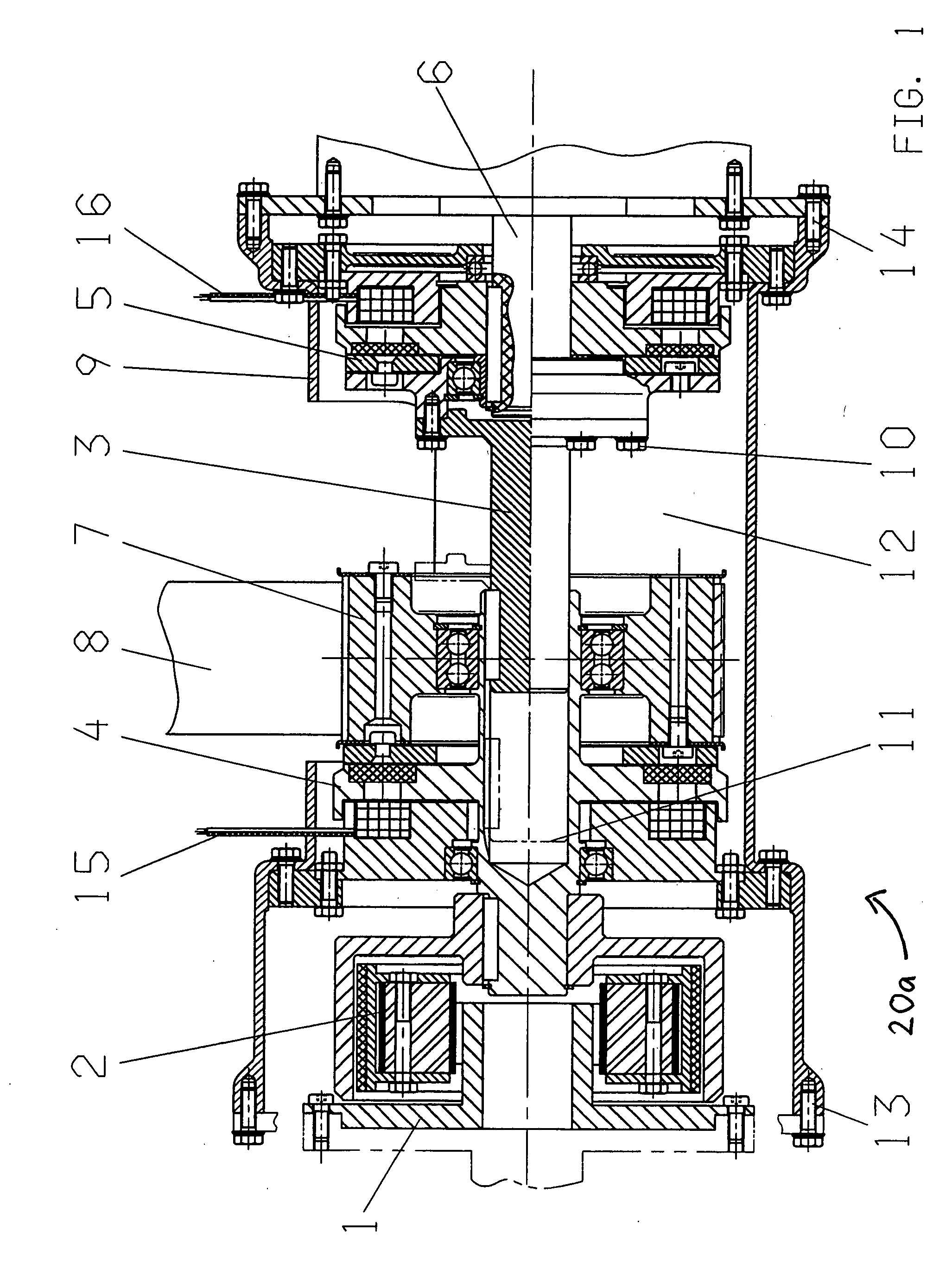
[0044] The transmission gearing for the selective torque transmission from one of the two internal-combustion engines to one or both generators includes two partial gearings which can be coupled by way of a belt drive and are arranged parallel to one another. The partial gearings have an essentially identical construction. FIG. 1 is a longitudinal sectional view of such a partial gearing 20a. The output shaft of the internal-combustion engine introduces the torque into the disk 1 with the hub. The—optional—centrifugal clutch 2 engages after the nominal rotational speed has been reached and thereby transmits the torque to the gear shaft 3 and the engine-side shifting clutch 4. When the generator arranged in line is to be driven, the clutch 4 remains open (not activated electrically or only quiescent current) and the generator-side shifting clutch 5 has to close. The torque is thereby transmitted to the generator shaft 6.

[0045] When only the generator situated in parallel is to be dr...


PUM


Abstract

A mobile, self-sufficient operating assembly for providing electrical energy which includes two internal-combustion engines (21, 23) as well as two generators (22, 24). The internal-combustion engines (21, 23) and the generators (22, 24) being mutually connected by way of a transmission gearing (20) having several shifting clutches (4, 4′, 5, 5′). Electrical control devices control the shifting clutches (4, 4′, 5, 5′) of the transmission gearing (20) whereby optionally each of the two internal-combustion engines (21, 23) or both internal-combustion engines (21, 23) together can drive each of the two generators (22, 24) or both generators (22, 24) together.

Description

BACKGROUND AND SUMMARY OF THE INVENTION [0001] This application claims the priority of Application No. 102 51 833.5-32, filed Nov. 7, 2002, in Germany, the disclosure of which is expressly incorporated by reference therein. [0002] The invention relates to a mobile, self-sufficient operating assembly for providing electrical energy, for example, for supplying mobile first-aid stations. [0003] Military tasks in the field of guidance and communication, particularly also sanitary services, which differ little from the civil application in the event of catastrophes, require highly mobile systems which are operable only by means of a reliable self-contained power supply. For higher power—150 Kw to a few MW, various manufacturers offer so-called power packs. They comprise the internal-combustion engine and generator components, which are both fixedly mounted usually in sound-proof containers, for example, for supplying power to construction sites and remote regions in the quasi-stationary ...

Claims


Application Information

Patent Timeline
Patent Type & Authority Applications(United States)
IPC IPC(8): F02B63/04H02J9/08
CPCF02B63/04Y10T74/19014H02J9/08F02B63/047
Inventor DULL, SEBASTIANFRITZSCHE, ALBERTSERDEN, ANDREASWASCHILEWSKI, GUNTHER
Owner EADS DEUT GMBH
Why Eureka
Try Eureka