Distal protection devices having controllable wire motion

Inactive Publication Date: 2005-01-13
TYCO HEALTHCARE GRP LP
View PDF22 Cites 103 Cited by
  • Summary
  • Abstract
  • Description
  • Claims
  • Application Information

AI Technical Summary

Benefits of technology

[0010] This invention is a distal protection device for use in a body lumen. The device includes a guidewire system which may include separate individual guidewire or elongate members. A functional element, such as a filter or occlusive device including a balloon is mounted on the guidewire system. The device is able to filter or occlude debris and blood clots in a body lumen and / or prevent them from moving distally and causing emboli. The various embodiments of the invention disclosed herein allow the user to accurately place the filter in the vessel and permit substantial guidewire movement during the filter use without dislodging the filter. Motion of the guidewire can be independent of the motion of the distal protection device and the contact force between the guidewire and the protection device can be cushioned in the device of this invention. In addition, in some of the embodiments disclosed herein the user of the device is able to enable or disable the relative motion feature between the guidewire and the protection device and / or to obtain tactile feedback to indicate the limit of the range of guidewire movement when the relative motion feature is enabled.
[0013] The functional element may include a proximal end connected to the second elongate member and a distal end connected to a distal slider which is slideable over the second elongate member, and further may include a loop at the distal end of the first elongate member which encircles the second elongate member between the proximal end of the functional element and the distal slider. The loop may be contained within the interior cavity. The connecting means may comprise the first elongate member having a tubular body having a lumen with an interior diameter and the second elongate member having a first region with an exterior diameter less than the interior diameter of the lumen of the tubular body, the first region being slideably received in the lumen of the tubular body. The second elongate member may have enlarged portions adjacent proximal and distal ends of the first region, which have an exterior diameter larger than the interior diameter of the lumen of the tubular body. At the first relative position, a first surface of the first elongate member can abut against a first surface of the second elongate member. This may further include means for gradually increasing resistance to movement between the first elongate member and the second elongate member as the first surface of the first elongate member is moved toward the first surface of the second elongate member.
[0016] In a third embodiment, this invention is a distal protection device for use in a body lumen comprising a first elongate member having distal and proximal ends; a second elongate member having distal and proximal ends; a functional element carried by the second elongate element, the functional element being expandable from a delivery configuration to an expanded deployed configuration when the functional element is deployed in the body lumen; and a sleeve having at least one lumen sized to slideably accommodate the first and second elongate members, the distal end of the first elongate member having a stop positioned distal to the at least one lumen and sized to prevent the distal end of the first elongate member from being withdrawn proximally from the at least one lumen, the second elongate member having a stop positioned proximal to the at least one lumen and sized to prevent the proximal end of the second elongate member from being withdrawn distally from the at least one lumen.
[0022] In a ninth embodiment, this invention is a method of making a guidewire system for delivery of a functional element to a desired location in a body lumen comprising providing a first elongate member, a second elongate member and a functional element; mounting the functional element on the second elongate member; and connecting the first elongate member to the second elongate member in a manner that permits the first elongate member to be moved with respect to the second elongate member without moving the second elongate member.
[0024] In an eleventh embodiment, this invention is a distal protection device for use in a body lumen comprising an elongate member having distal and proximal ends and at least one stop spaced proximally of the distal end; a functional element having a first slider disposed for translation along the elongate member between the stop and proximal end, the stop limiting translation of the slider in a distal direction; and means for gradually increasing the resistance between the slider and stop as the stop is moved proximally toward the slider.
[0027] In a thirteenth embodiment, this invention is a distal protection device for use in a body lumen comprising a first elongate member having distal and proximal ends; a second elongate member having distal and proximal ends; a functional element carried by the second elongate element, the functional element being expandable from a delivery configuration to an expanded deployed configuration when the functional element is deployed in the body lumen; and means for locking the first elongate member to the second elongate member, the locking means having a locked position where the relative positions of the first and second elongate members are locked and an unlocked position where the first elongate member can be moved over a range of motion from a first relative position to a second relative position without resulting in movement of the second elongate member.

Problems solved by technology

During vascular surgery or endovascular treatment of vessels including atherectomy, balloon angioplasty, and / or stent deployment, debris such as plaque and blood clots can move from the treatment site through a vein or artery, thus compromising the flow of blood at a location distal from the treatment site.
When catheters are exchanged inadvertent wire movement can cause the protection device to move within the vessel.
Excessive wire motion can also retract a protection device proximally, where it can potentially become entangled in a stent or even be inadvertently removed from the vessel being protected.
This is undesirable because captured emboli can be released and / or new emboli can be formed distal to the protection device, blood vessels can be damaged, and / or the device can entangle with an implant such as a stent.
Therefore, it is clear that too much movement of the device within the vessel could have catastrophic results.
While this system meets many of the needs in the art, it limits the range of motion of the filtration device on the guidewire, and the precision with which it can be placed is limited.
Another known limitation of distal protection devices relates to wire bias.
For filters this can defeat the protection effect by compressing the filter opening.
For occlusion devices the wire bias effect can cause excessive motion of the occlusion device with potential liberation of embolic debris from the vicinity of the occlusive element.
While this system meets many of the needs in the art, it adds bulk to the device and thereby limits crossing profile.

Method used


Image

  • Distal protection devices having controllable wire motion
  • Distal protection devices having controllable wire motion
  • Distal protection devices having controllable wire motion

Examples


Embodiment Construction

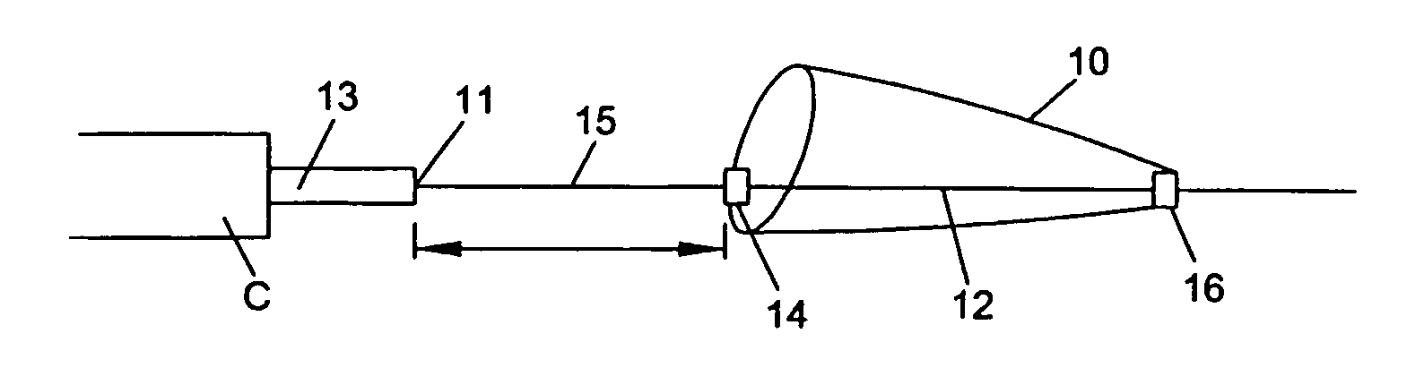
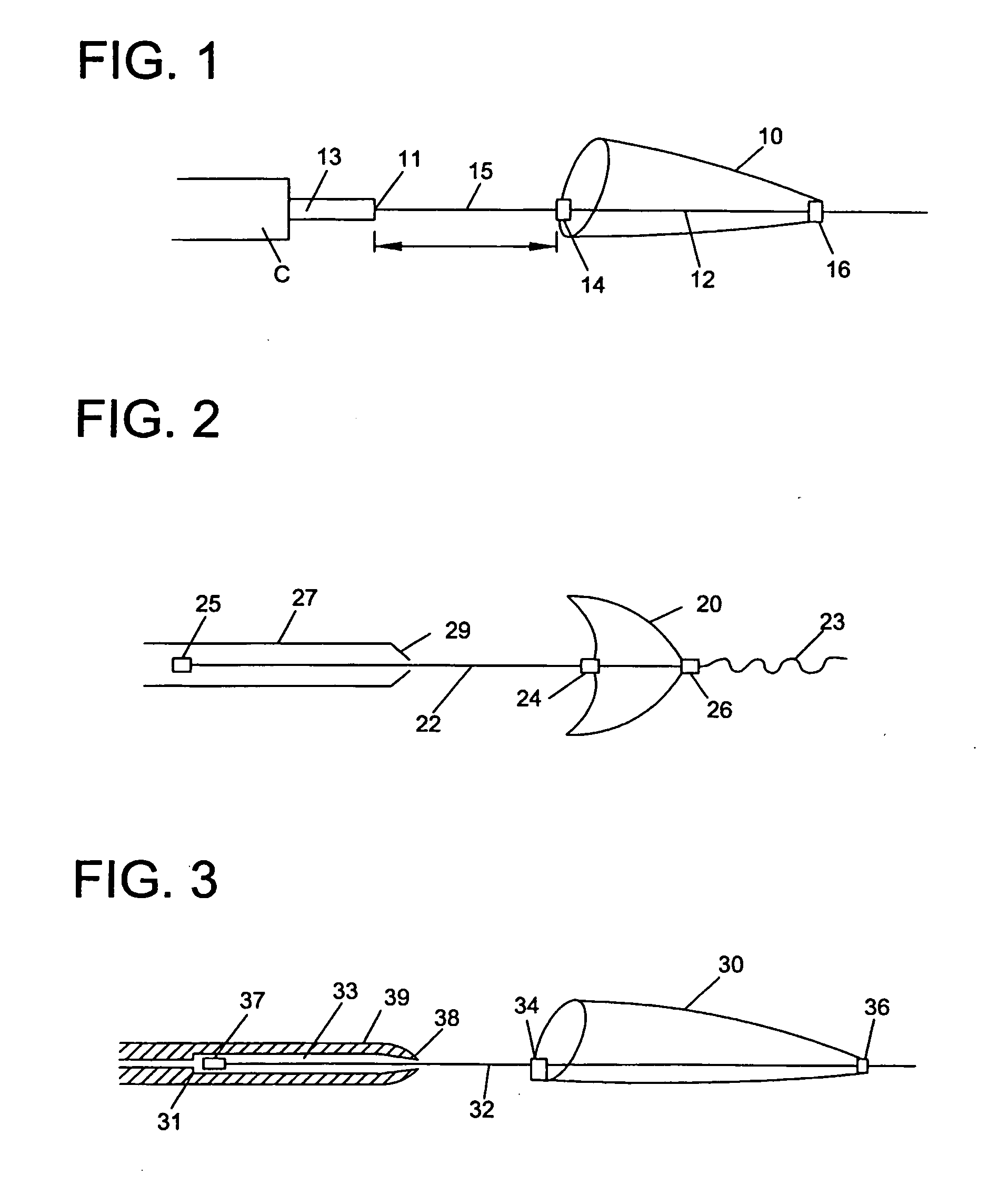
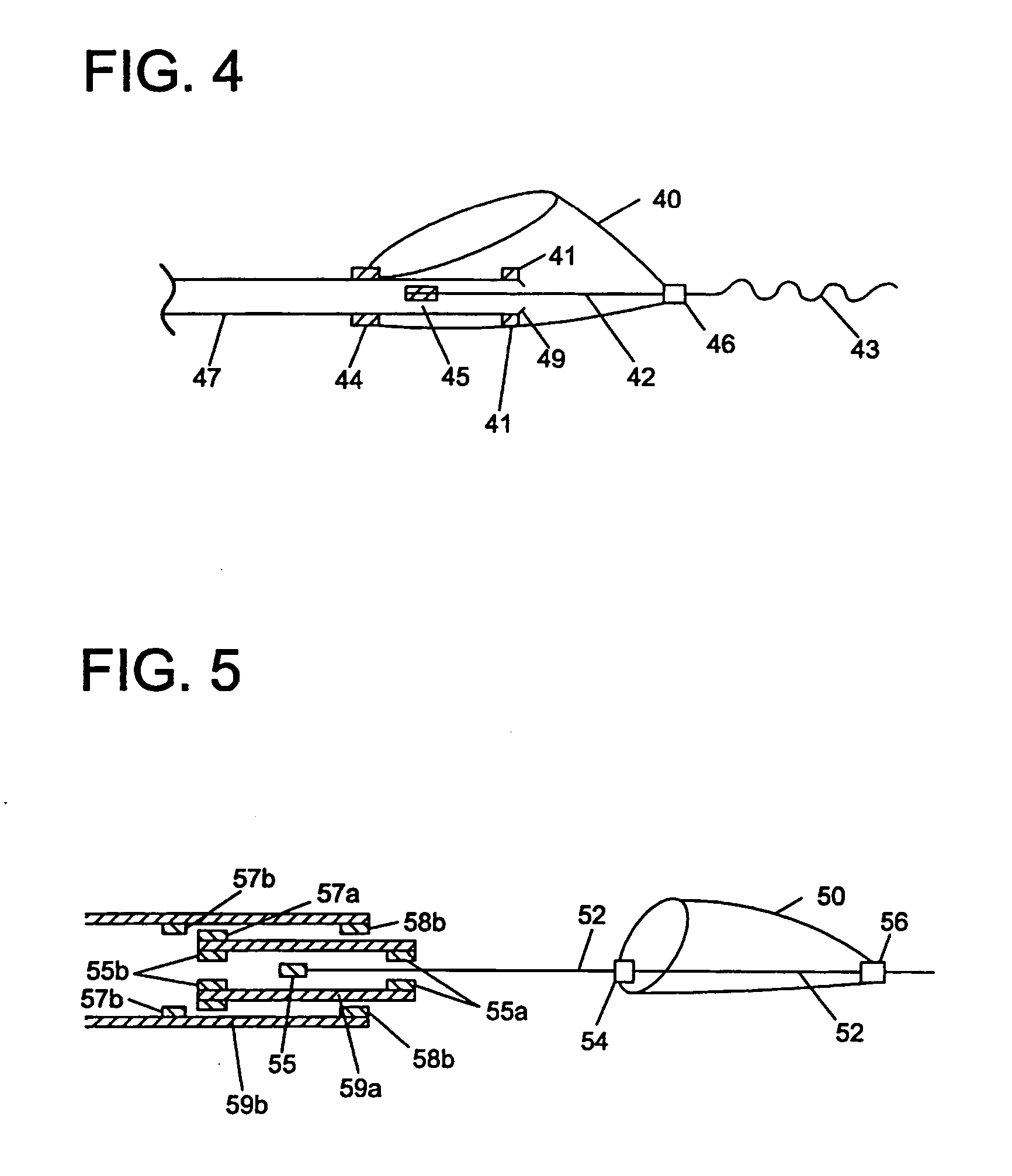
[0047] Various embodiments of the invention are disclosed herein. Some of the embodiments are directed to devices that allow independent movement of the guidewire with respect to the filter or other functional element once the functional element has been deployed. (FIGS. 1-14). Other embodiments are directed to devices having a braking feature. (FIGS. 15-18). Brakes provide a means to cushion the force when a wire, moving with very low friction relative to a filter, encounters a stop. The brake provides tactile feedback that the hard stop is approaching, and this tactile feedback allows the doctor to adjust the motion accordingly. Other embodiments include a shock absorbing feature. (FIGS. 19-27). Shock absorbers act as distance-accommodating springs that are not frictionally independent from the wire. Both allow feedback to the physician so the physician can avoid dislodging or disrupting the functional device by excessive movement of the guidewire carrying the device during a vasc...


PUM


Abstract

A distal protection device for use in a body lumen. The device includes a functional element which may be a filter or an occlusive element. The device includes means for controlling the movement and placement of the functional element along a guidewire. Motion of the guidewire can be independent of the motion of the functional element.

Description

CROSS-REFERENCE TO RELATED APPLICATION [0001] This Application is a divisional of application Ser. No. 10 / 093,572, filed Mar. 8, 2002, hereby incorporated herein by reference.FIELD OF THE INVENTION [0002] This invention relates to devices used in a blood vessel or other lumen in a patient's body. In particular, this invention relates to distal protection devices having a guidewire which can be controlled independently of a functional element such as a filter which is carried by the guidewire. BACKGROUND OF THE INVENTION [0003] During vascular surgery or endovascular treatment of vessels including atherectomy, balloon angioplasty, and / or stent deployment, debris such as plaque and blood clots can move from the treatment site through a vein or artery, thus compromising the flow of blood at a location distal from the treatment site. Various distal protection systems have been developed to prevent such debris from embolizing in the vessel. Such distal protection devices include filters ...

Claims


Application Information

Patent Timeline
IPC IPC(8): A61F2/01
CPCA61F2/013A61F2002/015A61M25/09A61M2025/0079A61F2230/0008A61F2230/0069A61F2230/008A61F2230/0093A61F2002/018A61M2025/09183
Inventor KUSLEIKA, RICHARD S.ADAMS, DANIEL O.ANDERSON, KENT D.NELSON, DALESANTER, JEFFREY D.
Owner TYCO HEALTHCARE GRP LP
Why Eureka
Try Eureka