
Brush seal with windage control

a brush seal and windage control technology, applied in the field of brush seals, can solve the problems of affecting the design of conventional brush seals, essentially useless flared bristles, and deformation of cold work bristles, so as to reduce windage effects, reduce effective seal length, and inhibit bristle flare

Inactive Publication Date: 2005-01-13
UNITED TECH CORP
View PDF11 Cites 30 Cited by
  • Summary
  • Abstract
  • Description
  • Claims
  • Application Information

AI Technical Summary

Benefits of technology

The present invention provides an improved brush seal with windage control and inhibits bristle flare in response to windage effects. The brush seal maintains an effective seal length despite windage effects and includes a set of non-contacting bristles that reduces windage effects on the first set of bristles. The brush seal also has a set of longer bristles adjacent a set of shorter bristles, with the shorter bristles located on a high pressure side of the longer bristles.

Problems solved by technology

Windage, however, can detrimentally affect such conventional brush seal designs.
Over time, these forces cold work the bristles.
In other words, the flared bristles essentially become useless since they no longer prevent fluid leakage through the gap.
This reduces the effectiveness of the brush seal.
Even with windage covers, bristles on the high pressure side still have exposure to windage and thus mushroom.

Method used


Image

  • Brush seal with windage control
  • Brush seal with windage control
  • Brush seal with windage control

Examples


Embodiment Construction

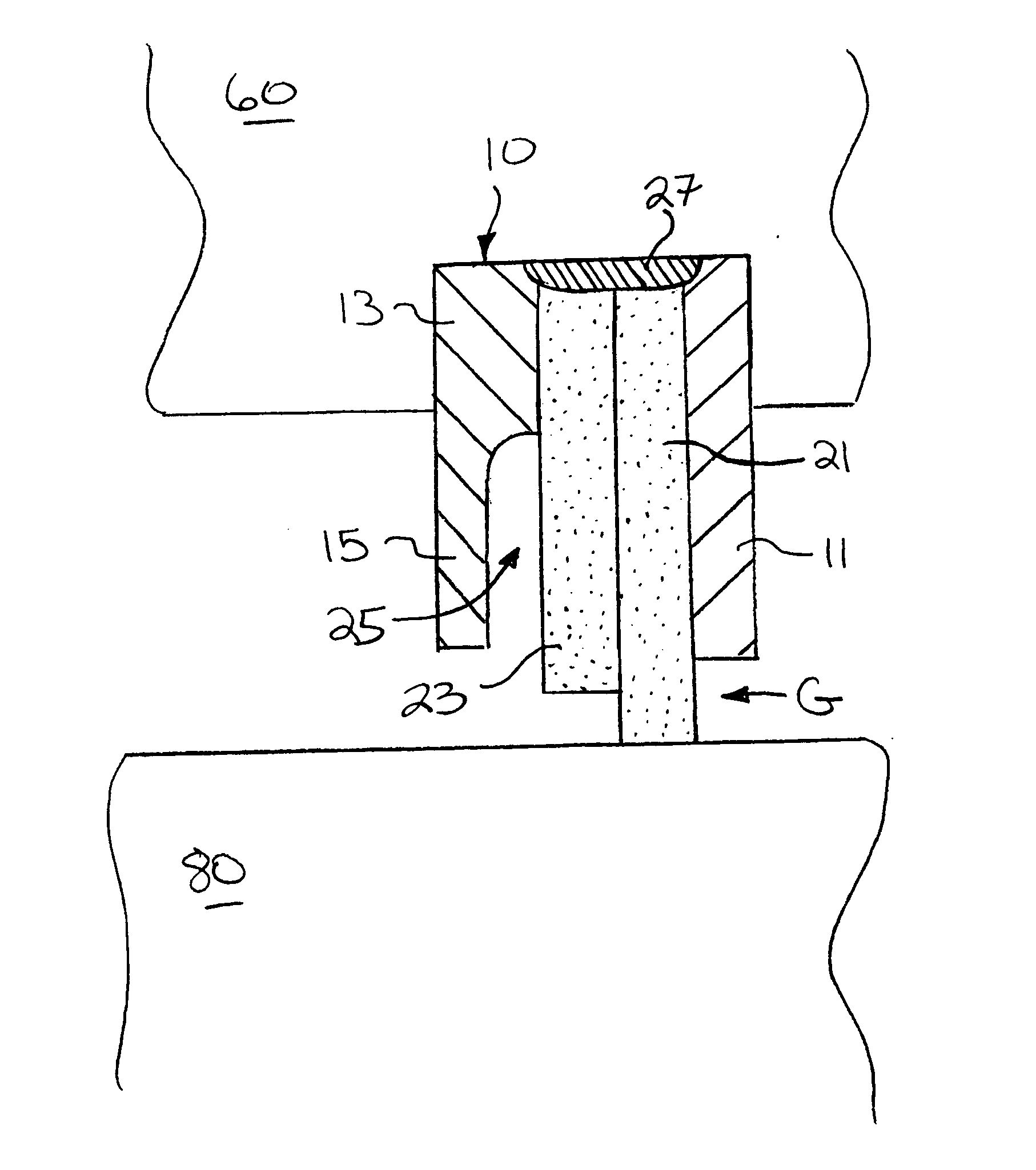
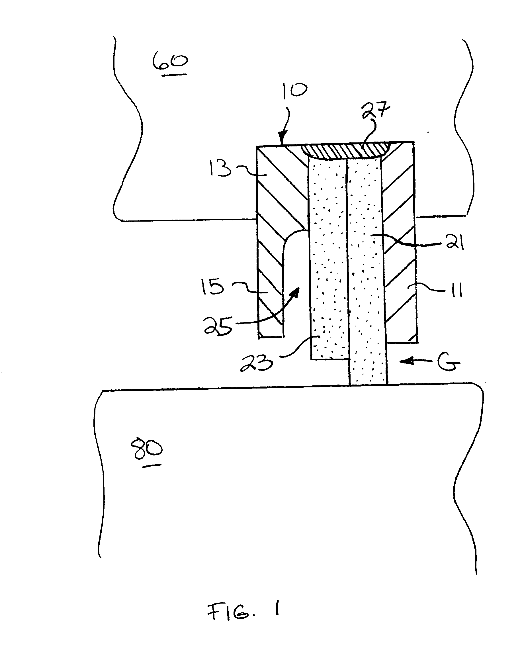
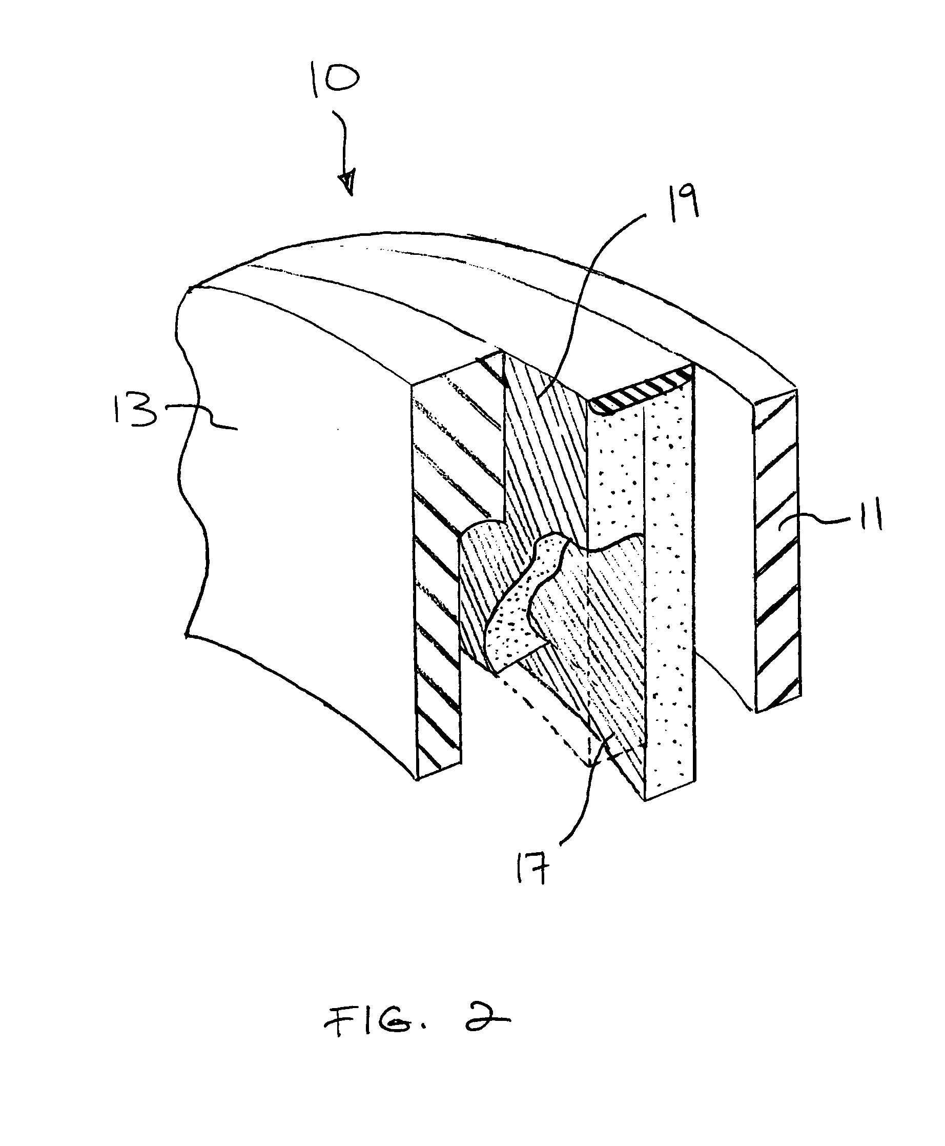
[0019]FIGS. 1-3 display one alternative embodiment of a brush seal 10 of the present invention. Although shown as a single stage, the brush seal 10 could have multiple stages. The brush seal 10 secures to a first component 60, such as a stationary component (e.g. a diffuser case) of a gas turbine engine, in conventional fashion and extends towards a second component 80, such as a rotating component (e.g. a rotor) of a gas turbine engine. The brush seal prevents fluid flow through a gap G between the components 60, 80 from a side at a high pressure location (the left side of FIG. 1) to a side at a low pressure location (the right side of FIG. 1).

[0020] The brush seal 10 includes a back plate 11 and side plate 13 made from suitable materials. The side plate 13 also preferably includes a windage cover 15. The windage cover 15 is preferably integral with the side plate 13, formed by undercutting the side plate 13. The windage cover extends from the side plate 13 towards the second comp...


PUM


Abstract

A brush seal with: a back plate; a side plate; a first set of bristles; and a second set of bristles between the first set of bristles and the side plate, The second set of bristles have a characteristic, different than the first set of bristles, that reduces windage effects on the first set of bristles. A brush seal for sealing a gap between first and second components, having: a back plate; a side plate; a set of contacting bristles that engages the second component; and a set of non-contacting bristles that extends towards, but does not engage, the second component. The non-contacting bristles reside between the contacting bristles and the side plate. In a brush seal having a set of longer bristles adjacent a set of shorter bristles, wherein the improvement comprises the shorter bristles located on a high pressure side of the longer bristles.

Description

BACKGROUND OF THE INVENTION [0001] This invention relates to brush seals. Specifically, the present invention relates to brush seal that have features to control windage. [0002] Brush seals prevent fluid flow through a gap between two components. The brush seal typically secures to the first component and has a pack of wire bristles that span the gap between the two components. The density of the bristle pack prevents leakage of the fluid through the gap. [0003] Windage, however, can detrimentally affect such conventional brush seal designs. Windage can lift, twist and bend the bristles. Over time, these forces cold work the bristles. Eventually, the bristles flare (also referred to as mushrooming or brooming). Flared bristles no longer make contact with the second component. This leaves fewer bristles to contact the second component. Fewer bristles contacting the second component decrease the effective thickness of the seal area. In other words, the flared bristles essentially beco...

Claims


Application Information

Patent Timeline
Patent Type & Authority Applications(United States)
IPC IPC(8): F16J15/32
CPCF16J15/3288
Inventor ADDIS, MARK E.
Owner UNITED TECH CORP
Learn More