
Rooftop opening safety railing

Active Publication Date: 2005-01-13
ACTIVAR CONSTR PROD GRP
View PDF15 Cites 19 Cited by
  • Summary
  • Abstract
  • Description
  • Claims
  • Application Information

AI Technical Summary

Benefits of technology

[0009] The present invention provides improved safety railings for use with an opening in a rooftop or other location. Safety railings are described that are easily securable to the curb, or upstanding wall, surrounding the opening. The securing mechanism of the safety railings also takes advantage of any outwardly protruding lip on the curb of the opening. In preferred embodiments described herein, the safety railing features a base portion that is reversibly securable to the curb portion of the opening and a railing portion that rises above the base portion. In one embodiment, the base portion includes side members with a square or rectangular cross-section t

Problems solved by technology

First, it provides only two upstanding handles and no surrounding rail.
Such connectors damage the opening since they penetrate it, thereby providing leakage points around the opening.
Also, an error in the length of the connectors used can create a problem.
If screws are used that are too long, they may present a puncturing hazard to persons or items passing through the opening.
If screws that are too short are used, the handles may fall off of their mounting while being gripped by a person, allowing the person to fall downward through the opening and perhaps be injured.
Unfortunately, this device is unsteady in practice since it relies upon four clamps that grip each of the corners of the curb surrounding a rooftop opening.
Over time, the railing may become unstable.
However, the fact that the railing may be pulled and pushed during use will virtually ensure that, over time, some damage will occur to the rooftop, regardless.

Method used


Image

  • Rooftop opening safety railing
  • Rooftop opening safety railing
  • Rooftop opening safety railing

Examples


Embodiment Construction

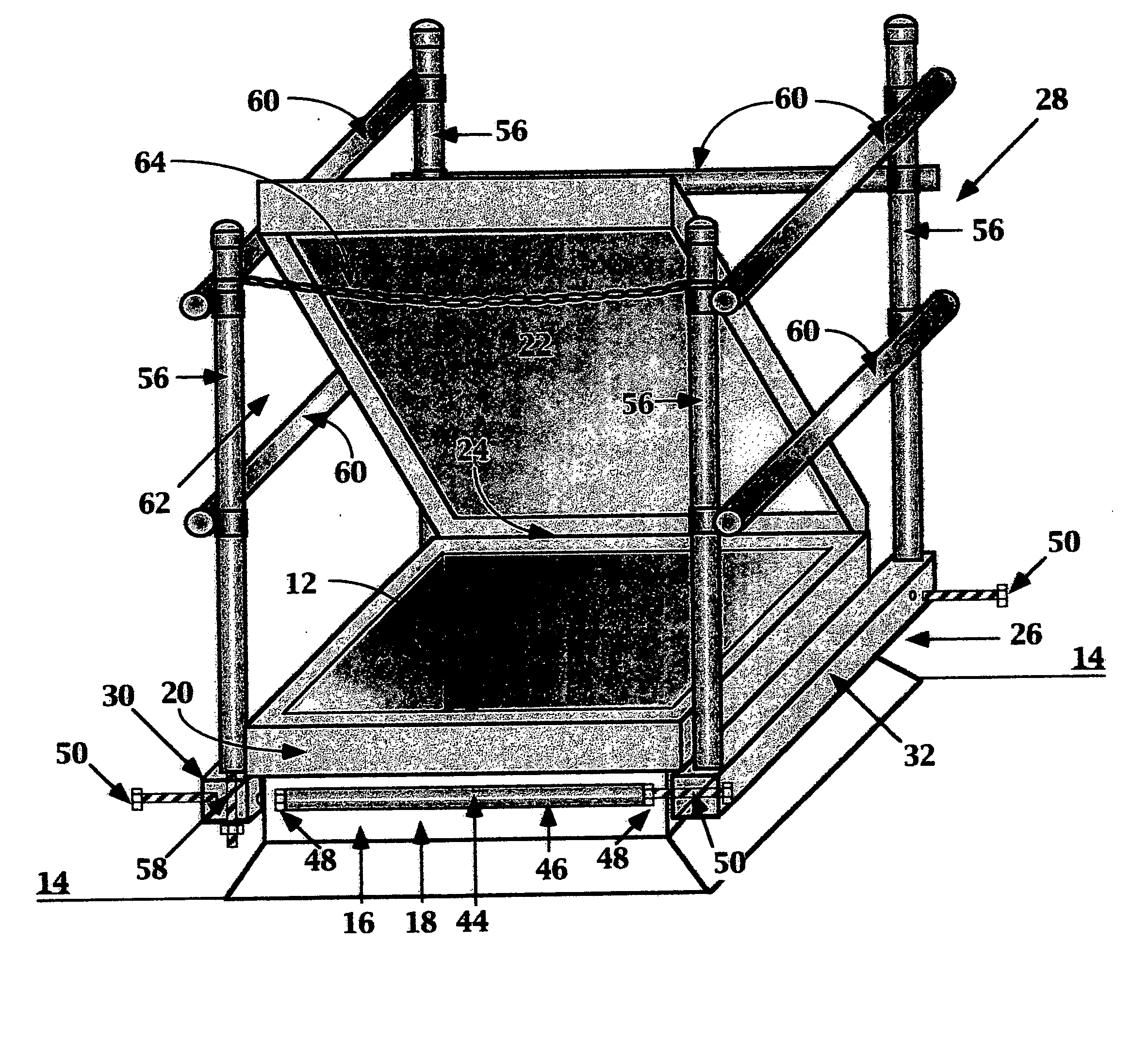
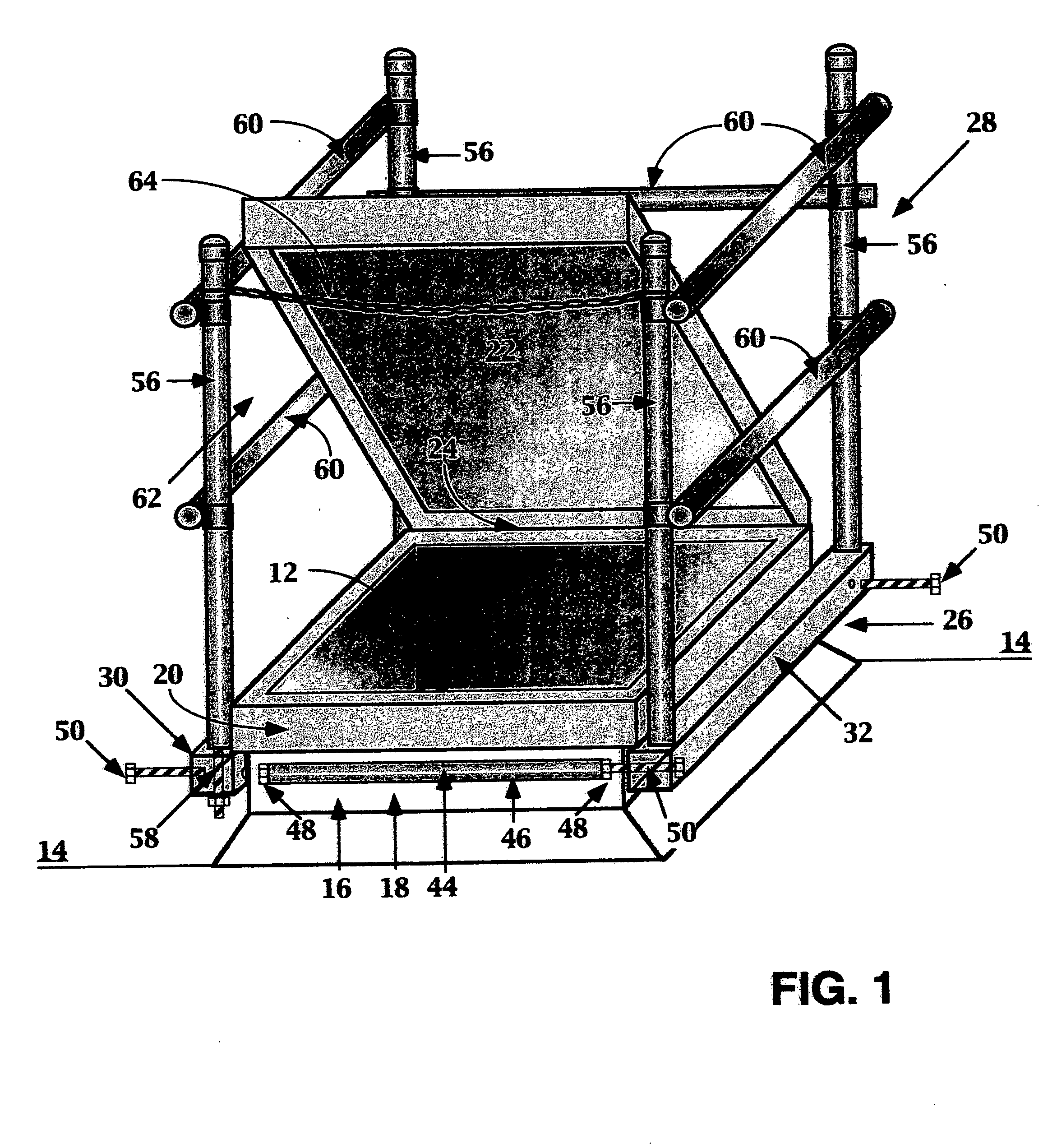
[0019]FIGS. 1-3 depict a first exemplary rooftop opening safety railing 10 in accordance with the present invention. It will be understood, however, that the safety railing 10 may also have equal applicability to openings that are disposed in floors or locations other than a rooftop and that the rooftop locale is merely provided by way of example to illustrate the invention. FIGS. 1 and 2 show an opening 12 that is disposed in a rooftop 14. The opening 12 has a curb 16 that surrounds the opening 12. The curb 16 has an upstanding wall portion 18 and an outwardly projecting lip 20. Such lips 20 are common on rooftop openings, although not present on all such openings. It is noted that the safety railing 10 is useful for either type of opening, although it is particularly useful for those having outwardly protruding lips. The opening 12 that is shown is a roof hatch, having a hatch cover 22 that may be pivoted about hinge 24 to be selectively opened and closed. The opening 12 often con...


PUM


Abstract

An improved safety railing for use with an opening in a rooftop or other location. The safety railing is easily securable to the curb, or upstanding wall, surrounding the opening. The securing mechanism of the safety railing also takes advantage of any outwardly protruding lip on the curb of the opening. The safety railing features a base portion that is reversibly securable to the curb portion of the opening and a railing portion that rises above the base portion. The base portion includes a pair of side members that are shaped and sized to abut the upstanding portion of the curb. Each of the curb members also present a surface to underlie the lip of the curb and engage it if the base portion is lifted. The base portion also includes two base members that interconnect the two side members. The base members are preferably formed of round hollow stock and have threaded nuts welded to each axial end. Threaded bolts are used to affix the side members to the base members. Further, the base portion of the device provides a somewhat flexible joint and pretensioning mechanism that preclude significant bending of the base members after significant use.

Description

[0001] This application claims the priority of U.S. provisional patent application Ser. No. 60 / 485,418 filed Jul. 8, 2003.BACKGROUND OF THE INVENTION [0002] 1. Field of the Invention [0003] The invention relates generally to fall protection devices. In particular aspects, the invention relates to devices and methods for providing secure safety railings around hatches, skylights and other openings that are typically found on rooftops, but which may also be found in floors or other areas. [0004] 2. Description of the Related Art [0005] Railings and fall protection devices are important safety measures for use around rooftop openings, such as hatches. They ensure that persons passing through the opening have handholds and are intended to prevent a person from inadvertently falling into the opening. An example of a typical prior art safety arrangement is shown in U.S. Pat. No. 6,167,659 issued to Swindell, III, which describes a roof or access hatch safety system that is secured to the ...

Claims


Application Information

Patent Timeline
IPC IPC(8): E04D13/03E04F11/18E04G21/32
CPCE04G21/3204E04D13/0335
Inventor CUCCURULLO, JOSEPH
Owner ACTIVAR CONSTR PROD GRP
Learn More