
Method of manufacturing a hollow blade for a turbine engine

a technology of turbine engines and hollow blades, which is applied in the direction of turbines, liquid fuel engines, forging/pressing/hammering apparatus, etc., can solve the problems of relatively high implementation costs of manufacturing methods via forging, high material cost and machining costs, and low efficiency of manufacturing methods. , to achieve the effect of reducing manufacturing costs, facilitating implementation and reducing manufacturing costs

Active Publication Date: 2005-01-13
SN DETUDE & DE CONSTR DE MOTEURS DAVIATION S N E C M A
View PDF20 Cites 19 Cited by
  • Summary
  • Abstract
  • Description
  • Claims
  • Application Information

AI Technical Summary

Benefits of technology

The invention proposes a method of manufacturing hollow blades for turbine engines that reduces manufacturing costs compared to prior art methods. The method involves making two external parts, each bearing a rotor blade part and a foot part, and assembling them using diffusion bonding. The primary elements of the external parts are made using forging techniques, while the secondary elements are made using extrusion. The secondary elements are not intended to enter into the constitution of the rotor blade part of the external part, which reduces manufacturing costs. The method also includes stages of airfoil profiling and bulging to create the desired shape of the blade preform. The invention provides a more cost-effective way to manufacture hollow blades for turbine engines.

Problems solved by technology

Thus, the manufacturing of the external parts intended to constitute at least partially the blade preform, for example obtained via lamination, generates very high material costs and machining costs, and hence this method of manufacturing the hollow blade is not completely optimised.
However, this manufacturing technique via forging is relatively expensive to implement, as always due to the need to obtain parts each bearing an uneven thickness.

Method used


Image

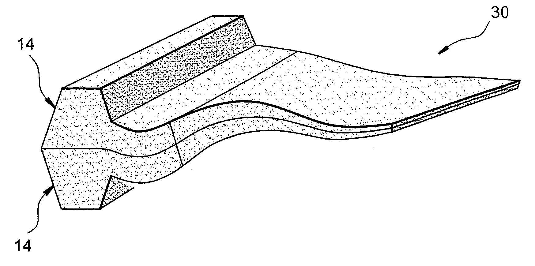
  • Method of manufacturing a hollow blade for a turbine engine
  • Method of manufacturing a hollow blade for a turbine engine
  • Method of manufacturing a hollow blade for a turbine engine

Examples


Embodiment Construction

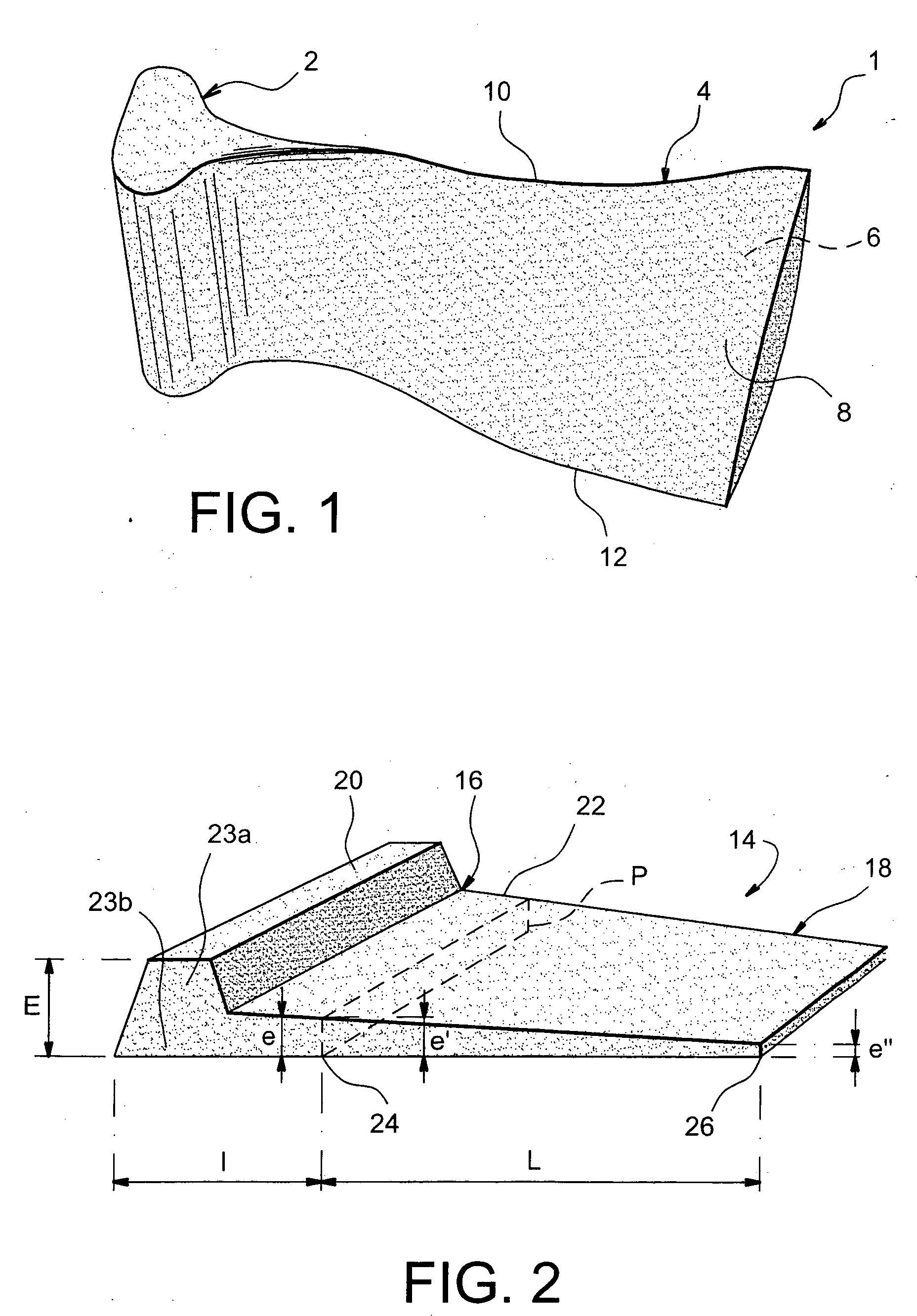
In reference to FIG. 1, we can notice a standard hollow blade 1 for turbine engine (not represented), for example made in titanium or in one of its alloys.

This hollow blade 1, of fan rotor blade type with large chord, comprises a foot 2 extended by a rotor blade 4 in a radial direction.

The rotor blade 4, intended to be placed in the circulation path of an airflow of the turbine engine, has two external surfaces 6 and 8, respectively called upper surface 6 and lower surface 8, connected by a leading edge 10 and a trailing edge 12.

FIG. 2 represents an external part 14 of a blade preform, such as the one intended to be obtained following a production stage of two external parts 14, during the implementing of the method of manufacturing according to the invention.

This external part 14 comprises a foot part 16 of variable and large thickness, which is extended in a radial direction by a rotor blade part 18. As can be seen in FIG. 2, the foot part 16 has an internal radial section...


PUM

PropertyMeasurementUnit
gas pressureaaaaaaaaaa
thickaaaaaaaaaa
thicknessaaaaaaaaaa

Abstract

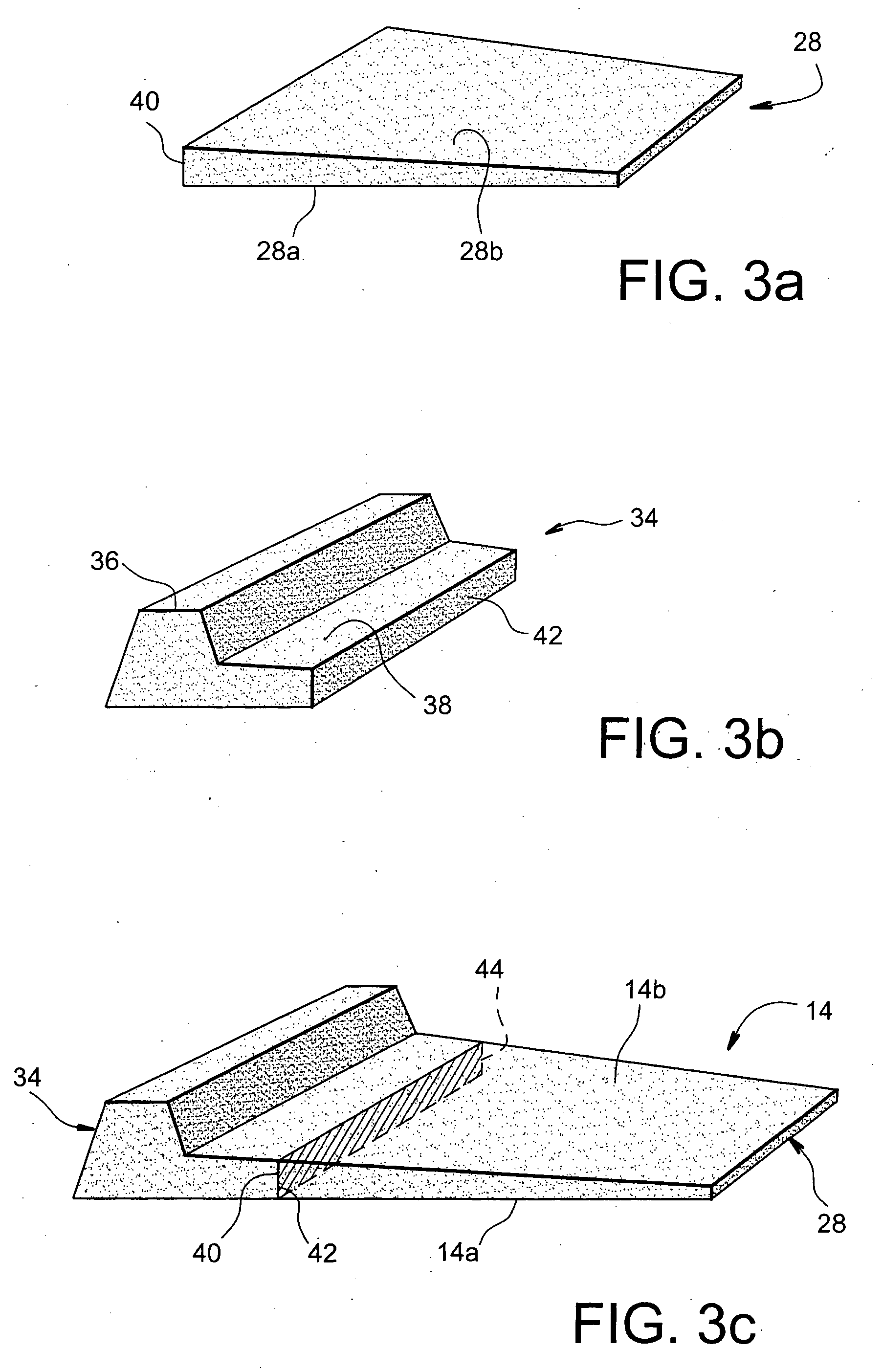
The invention relates to a method of manufacturing a hollow blade for turbine engine comprising a foot and a rotor blade, the method comprising a production stage of two external parts (14) as well as an assembling stage via diffusion bonding of these two external parts so as to obtain a blade preform. According to the invention, the production stage of the two external parts comprises, for each of these parts, the following operations: the making via forging of a primary element (28) constituting at least a rotor blade part of the external part; the making via forging of at least a secondary element (34) intended to form at least partially a foot part of the external part; and the assembling of each secondary element (34) onto the primary element so as to obtain the external part.

Description

TECHNICAL FIELD The invention generally relates to the field of methods of manufacturing blades for turbine engine, such as hollow fan blades, or any other type of rotor or stator blades for turbine engine. STATE OF THE PRIOR ART Usually a hollow fan blade for turbine engine comprises a relatively thick foot used to attach this blade into a rotor disk, this foot being radially extended towards the outside by a thin aerodynamic part, called rotor blade. From the prior art we know a method of manufacturing such a hollow blade, principally based on the use of the diffusion bonding technique, associated with that of superplastic forming. Indeed, in this method of the prior art, two or three component parts of the blade are firstly defined, then made separately before being stacked and assembled to each other via the diffusion bonding technique, with the purpose of obtaining a preform of the desired blade. Subsequently, it is proceeded with an airfoil profiling of the previously fab...

Claims


Application Information

Patent Timeline
Patent Type & Authority Applications(United States)
IPC IPC(8): F02C7/00B23K20/02B23P15/04F01D5/14F04D29/38
CPCB23K20/023B23K2201/001Y10T29/4932F01D5/147Y10T29/49339B23P15/04B23K2101/001
Inventor FERTE, JEAN-PIERREFRANCHET, JEAN-MICHELLHOMME, DANIELLORIEUX, ALAIN
Owner SN DETUDE & DE CONSTR DE MOTEURS DAVIATION S N E C M A
Learn More