
Bi-point detection type heart-rate monitor and its heart-rate monitoring method

a heart-rate monitor and detection type technology, applied in the field of heart-rate monitors, can solve the problems of circuit to make an erroneous judgment, design does not fit people of different body sizes (adults and children),

Inactive Publication Date: 2005-01-06
CHEN YOW PRECISE IND
View PDF8 Cites 41 Cited by
  • Summary
  • Abstract
  • Description
  • Claims
  • Application Information

AI Technical Summary

Benefits of technology

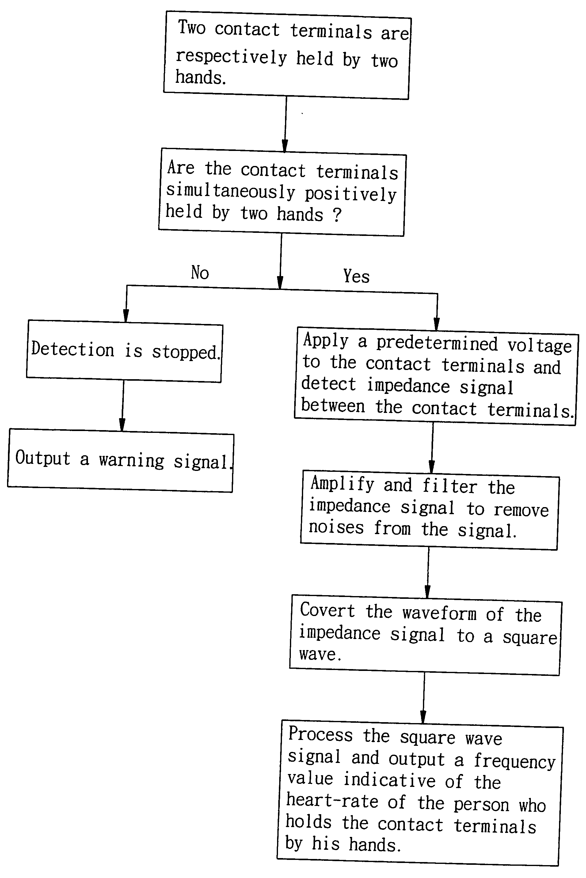
[0008] It is the main object of the present invention to provide a bi-point detection type heart-rate monitor, which uses two contact terminals for the touching of the user's two hands or two legs to obtain a single signal for heart-rate measuring without through a dual-signal comparison procedure as seen in prior art designs. Because each hand or leg needs only to touch one single terminal, the problem of contact error is eliminated.

Problems solved by technology

However, this design does not fit people of different body sizes (adults and children).
Due to the interference of such a false value, an inaccurate heart-rate is produced, as shown in FIG. 1, causing the circuit to make an erroneous judgment.

Method used


Image

  • Bi-point detection type heart-rate monitor and its heart-rate monitoring method
  • Bi-point detection type heart-rate monitor and its heart-rate monitoring method
  • Bi-point detection type heart-rate monitor and its heart-rate monitoring method

Examples


Embodiment Construction

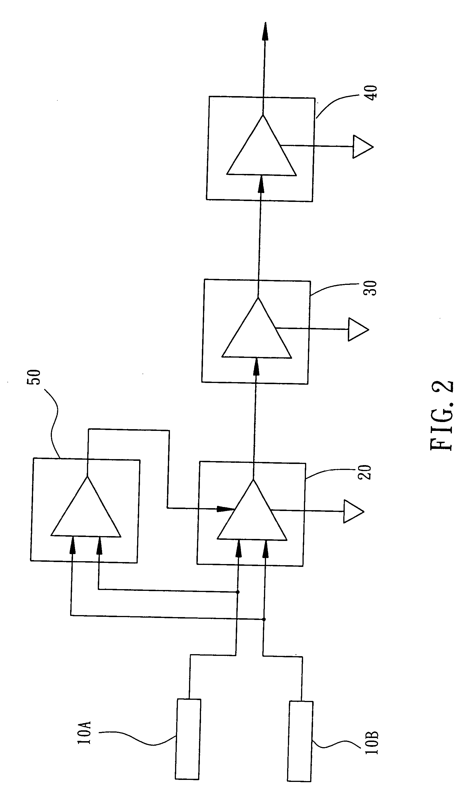
[0017] Referring to FIG. 2, a bi-point detection type heart-rate monitor in accordance with the present invention is generally comprised of two contact terminals 10A and 10B, an amplifier-filter circuit 20, a waveform converter 30, a processing and output circuit 40, and a detection unit 50.

[0018] The contact terminals 10A and 10B are electrically conducting terminals for the touching of the two hands or feet of the user (the person to be examined), i.e., the user works as a bioelectrical impedance connected between the contact terminals 10A and 10B when touching the contact terminals 10A and 10B accurately.

[0019] The amplifier-filter circuit 20 is adapted to apply a predetermined voltage to between the contact terminals 10A and 10B (enabling electric current to pass through the user's body), to sample impedance signal between the contact terminals 10A and 10B, and to amplify the impulse (i.e., the R wave) of the sampled impedance signal produced due to the beating of the user's h...


PUM


Abstract

A bi-point detection type heart-rate monitor is constructed to include two electrically conductive contact terminals for the touching of the two hands or feet of a person, an amplifier-filter circuit adapted to sample impedance signal between the contact terminals, to amplify the impulse of the sampled impedance signal, and to remove noises from the sampled impedance signal, a waveform converter adapted to rectify outputted waveform from the amplifier-filter circuit into a square wave, and a processing and output circuit adapted to receive and process the square wave signal outputted by the wave form converter, to obtain the mean frequency of peaks of the received square wave signal by means of a computing process, and to output the frequency value thus obtained to a display unit for display.

Description

BACKGROUND OF THE INVENTION [0001] 1. Field of the Invention [0002] The present invention relates generally to a heart-rate monitor adapted to monitor the frequency of a beating heart and, more particularly, to a bi-point detection type heart-rate monitor. The invention relates also to the heart-rate monitoring method used in the monitor. [0003] 2. Description of the Related Art [0004] Heart-rate monitoring technology and apparatus have been well developed in medical care industry. In recent years, heart-rate monitoring devices have been intensively used in exercising machines, recreational apparatus, home apparatus, as well as personal apparatus. For example, advanced treadmills and standing bicycles have their handlebars provided with sensor means that detect the frequency of the beating of the user's heart. Therefore, the user can monitor one's heart-rate during exercise, knowing one's physical status. There are known weight scales having heart beat sensor means. When measuring t...

Claims


Application Information

Patent Timeline
Patent Type & Authority Applications(United States)
IPC IPC(8): A61B5/024A61B5/276
CPCA61B5/02433A61B5/02444A61B5/6887A61B5/6843A61B5/0424A61B5/276
Inventor LIN, ABDADA
Owner CHEN YOW PRECISE IND
Learn More