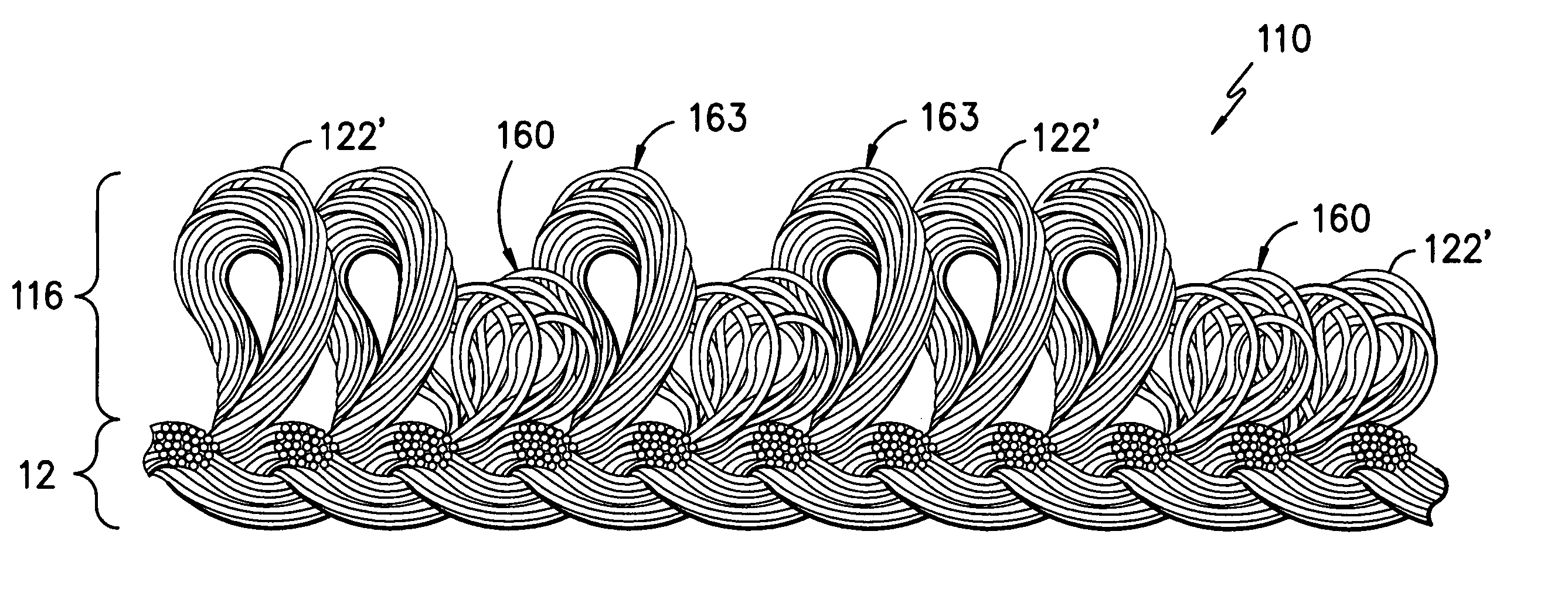
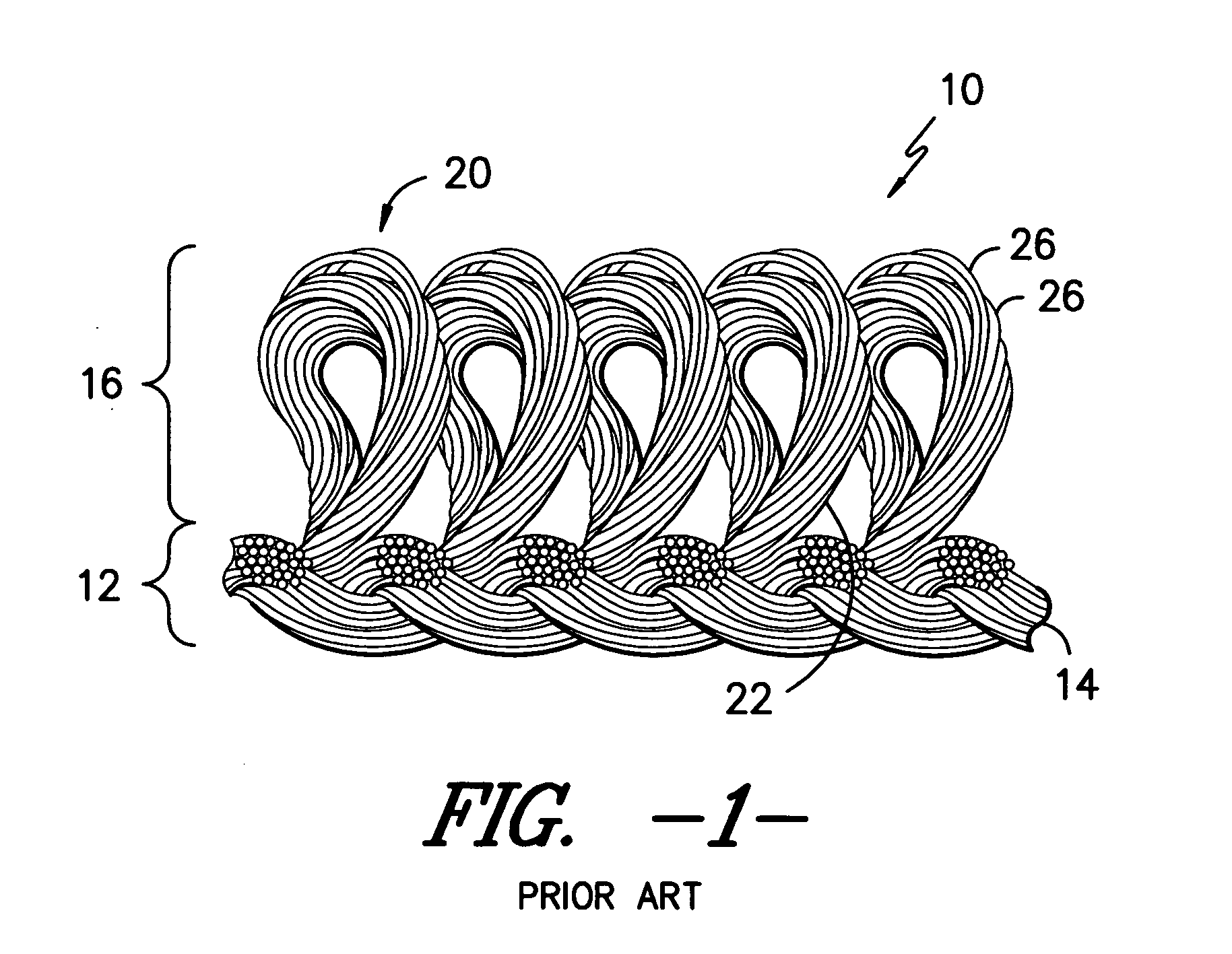
Loop pile fabric having randomly arranged loops of variable height
a technology of loops and loops, applied in the field of loop pile fabrics, can solve the problems of little if any benefit, inability to provide the appearance of random occurrence, and insufficiently aid in providing a textured feel to the fabric, and achieve the effect of reducing crystalline orientation and variable shrinking characteristics
- Summary
- Abstract
- Description
- Claims
- Application Information
AI Technical Summary
Benefits of technology
Problems solved by technology
Method used
Image

Examples
example
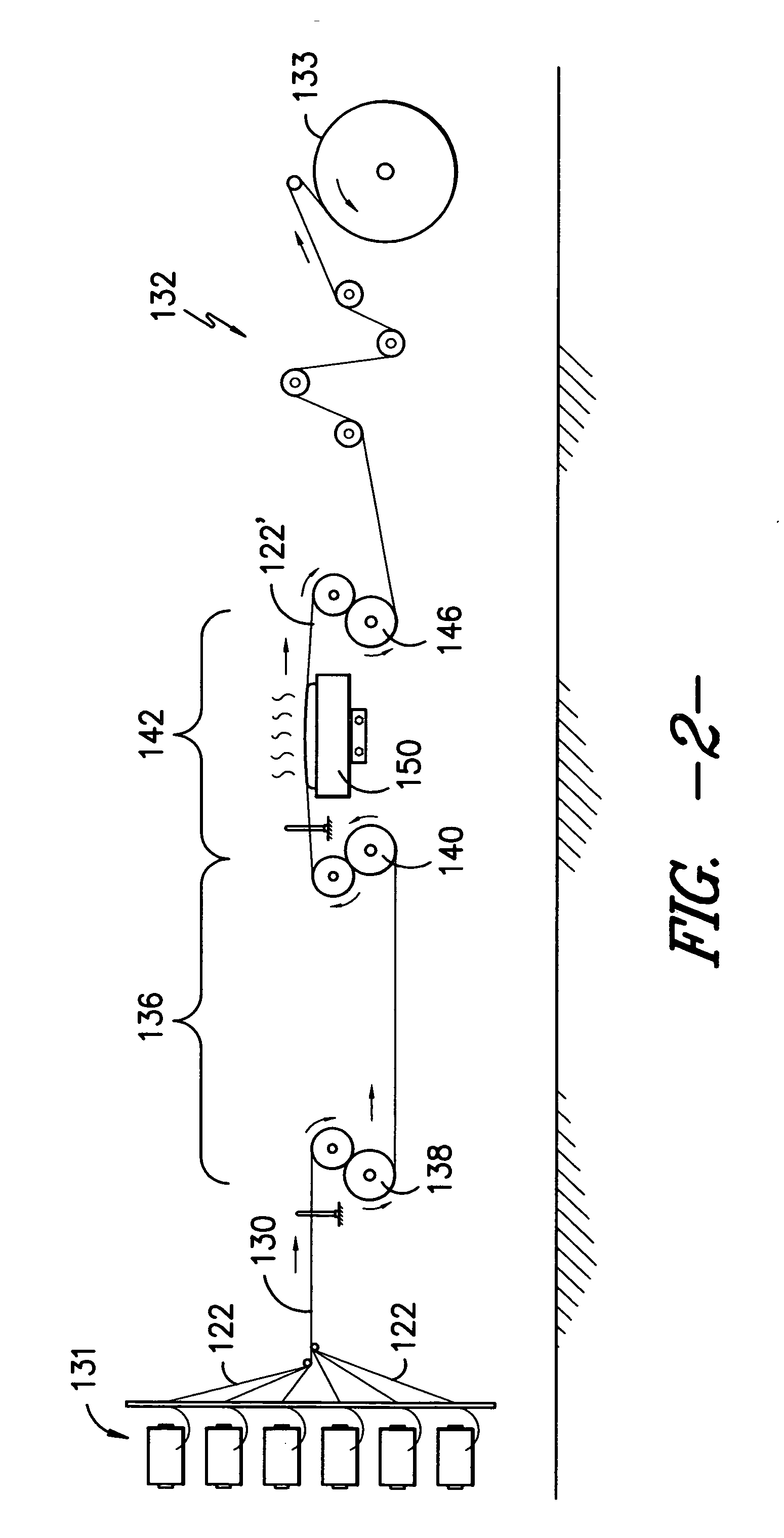
A 115 denier 36 filament semi-dull round partially oriented polyester yarn was subjected to a 1.143 draw across a contact Dowtherm heater plate operated at a temperature of 170 C. The heater contact length was 17 inches and the yarn was taken up off of the heater at a rate of 600 yards per minute. The yarns were spaced at a density of approximately 17.4 yarns per inch across the heater. The warper tension was set at 26 to 30 grams. Overall draw ratio was 1.165. Measurements of the post drawn yarn indicated a linear density of 103.6 denier, a boiling water shrinkage of 11.16%, an elongation of 87.46% and a breaking strength of 267 grams. The drawn yarn was knitted into the face of a 2 bar 56 gauge POL knit fabric with the ground being formed of a single ply 150 denier 36 filament semi-dull round false twist textured polyester. The bar 1 (face yarn) runner length was 136 inches. The bar 2 (ground yarn) runner length was 55 inches. The knitting machine was fully threaded. The resultan...
PUM
| Property | Measurement | Unit |
|---|---|---|
| temperature | aaaaa | aaaaa |
| elongation | aaaaa | aaaaa |
| height | aaaaa | aaaaa |
Abstract
Description
Claims
Application Information
 - R&D
- Intellectual Property
- Life Sciences
- Materials
- Tech Scout
- Unparalleled Data Quality
- Higher Quality Content
- 60% Fewer Hallucinations
Browse by: Latest US Patents, China's latest patents, Technical Efficacy Thesaurus, Application Domain, Technology Topic, Popular Technical Reports.
© 2025 PatSnap. All rights reserved.Legal|Privacy policy|Modern Slavery Act Transparency Statement|Sitemap|About US| Contact US: help@patsnap.com