Eureka AIR delivers breakthrough ideas for toughest innovation challenges, trusted by R&D personnel around the world.

X-ray imaging apparatus with continuous, periodic movement of the radiation detector in the exposure plane

a radiation detector and x-ray imaging technology, applied in the field of x-ray equipment, can solve the problems of insufficient medical applications, insufficient manufacturing of large-format semiconductor substrates, and inability to meet the requirements of large-scale semiconductor substrates, and achieve the effect of rapid exposure of comparatively large x-ray images

Inactive Publication Date: 2005-01-06
SIEMENS AG
View PDF12 Cites 10 Cited by
  • Summary
  • Abstract
  • Description
  • Claims
  • Application Information

AI Technical Summary

Benefits of technology

[0010] An object of the present invention is to provide an economical X-ray apparatus having a digital X-ray detector that enables a rapid exposure of comparatively large X-ray images.
[0012] Because the X-ray detector is not moved in step-by-step fashion, but instead is moved in continuously periodic fashion, the time required in conventional systems for frequent braking and re-acceleration of the X-ray detector is saved. In this way, the exposure time is significantly reduced.
[0014] The synchronous movement of the surface segment with the X-ray detector has the result that only the area to be imaged is exposed to the X-ray radiation. The overall X-ray radiation exposure of a patient to be examined is reduced in this way.
[0015] The movement of the surface segment to be exposed in the exposure plane preferably takes place by the displacement of a diaphragm system connected downstream from an X-ray source of the exposure unit. Such a displaceable diaphragm system enables an especially simple, quasi-arbitrary, and quasi-instantaneous shifting of the surface segment to be exposed, especially since the diaphragm or diaphragms of the diaphragm system themselves have extremely low inertia and thus can be driven rapidly. Alternatively or in addition to displacing the surface segment, it is possible to move the overall exposure unit, i.e., the X-ray source and the diaphragm system.
[0023] Among advantages achieved by the present invention are in particular that at a comparatively low cost an X-ray apparatus is realized employing a digital exposure technology that enables the particularly rapid exposure of comparatively large-format images. By movement of the X-ray detector within the exposure plane, the exposure of large-format images is enabled using a comparatively small detector surface. This permits the use of economical X-ray detectors that can be manufactured using conventional semiconductor substrates such as those that are mass-produced for consumer electronics applications. The continuously periodic drive of the X-ray detector results in a significant acceleration of the exposure process, since the X-ray detector does not have to be braked and re-accelerated for each partial exposure. The synchronous movement of the surface segment to be exposed by displacement of the diaphragm system or the movement of the overall exposure unit has the advantage that only those regions of the exposure plane at which an exposure is supposed to take place are exposed to X-ray radiation. In particular, the described X-ray apparatus facilitates dynamic X-ray exposures, i.e., the recording of moving X-ray images.

Problems solved by technology

Generally, however, such a semiconductor substrate manufactured for consumer electronics has only comparatively small dimensions (typically approximately 20×20 cm), which is often insufficient for medical applications.
The manufacture of large-format semiconductor substrates, which would be suitable specifically for the sizes required in medical applications, is hardly possible at reasonable cost due to the relatively small piece counts involved.
This production method is still very complicated and therefore expensive.
A disadvantage of this is that a considerable period of time is required for the detector to scan the entire imaged surface.

Method used


Image

  • X-ray imaging apparatus with continuous, periodic movement of the radiation detector in the exposure plane
  • X-ray imaging apparatus with continuous, periodic movement of the radiation detector in the exposure plane
  • X-ray imaging apparatus with continuous, periodic movement of the radiation detector in the exposure plane

Examples


Embodiment Construction

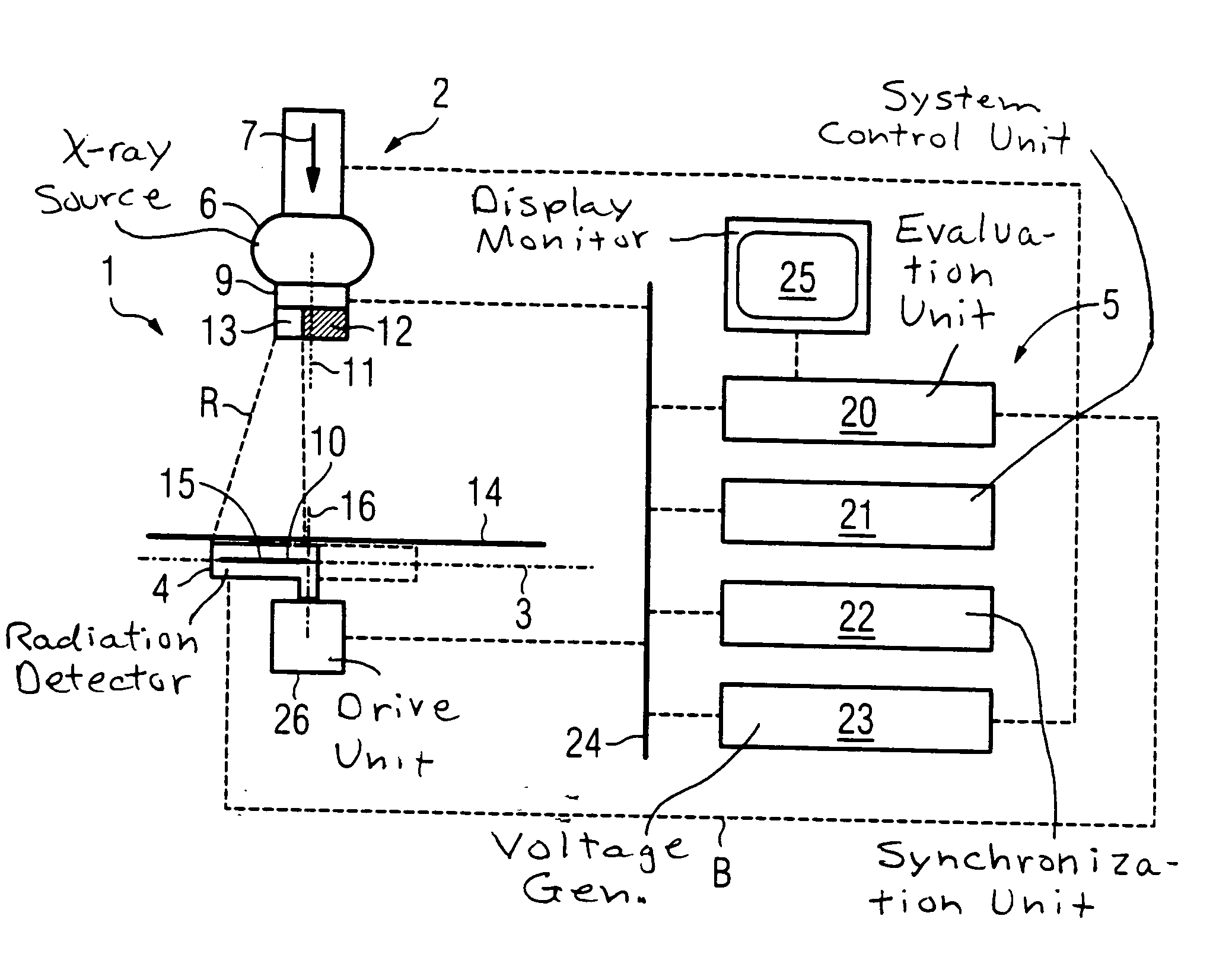
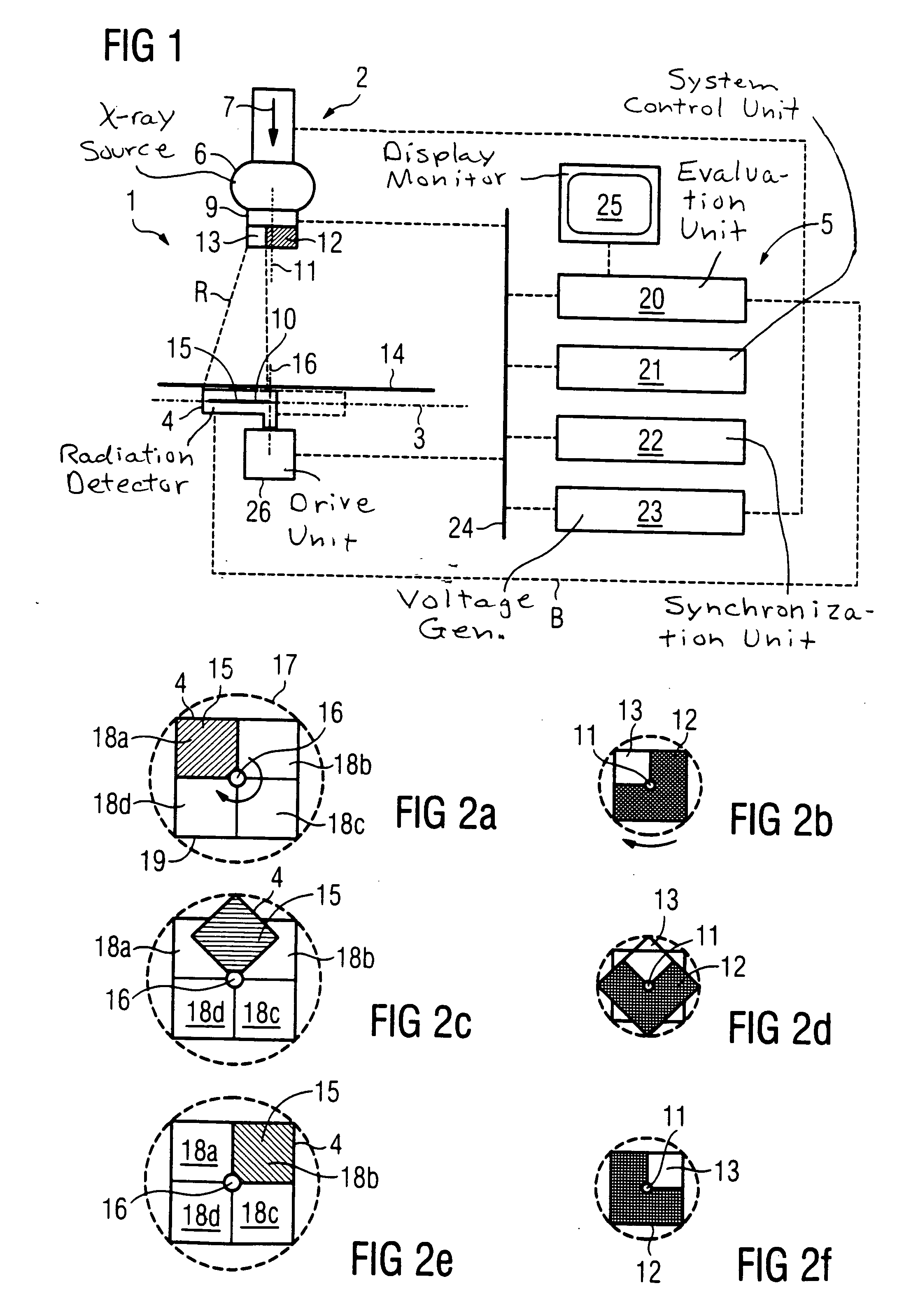
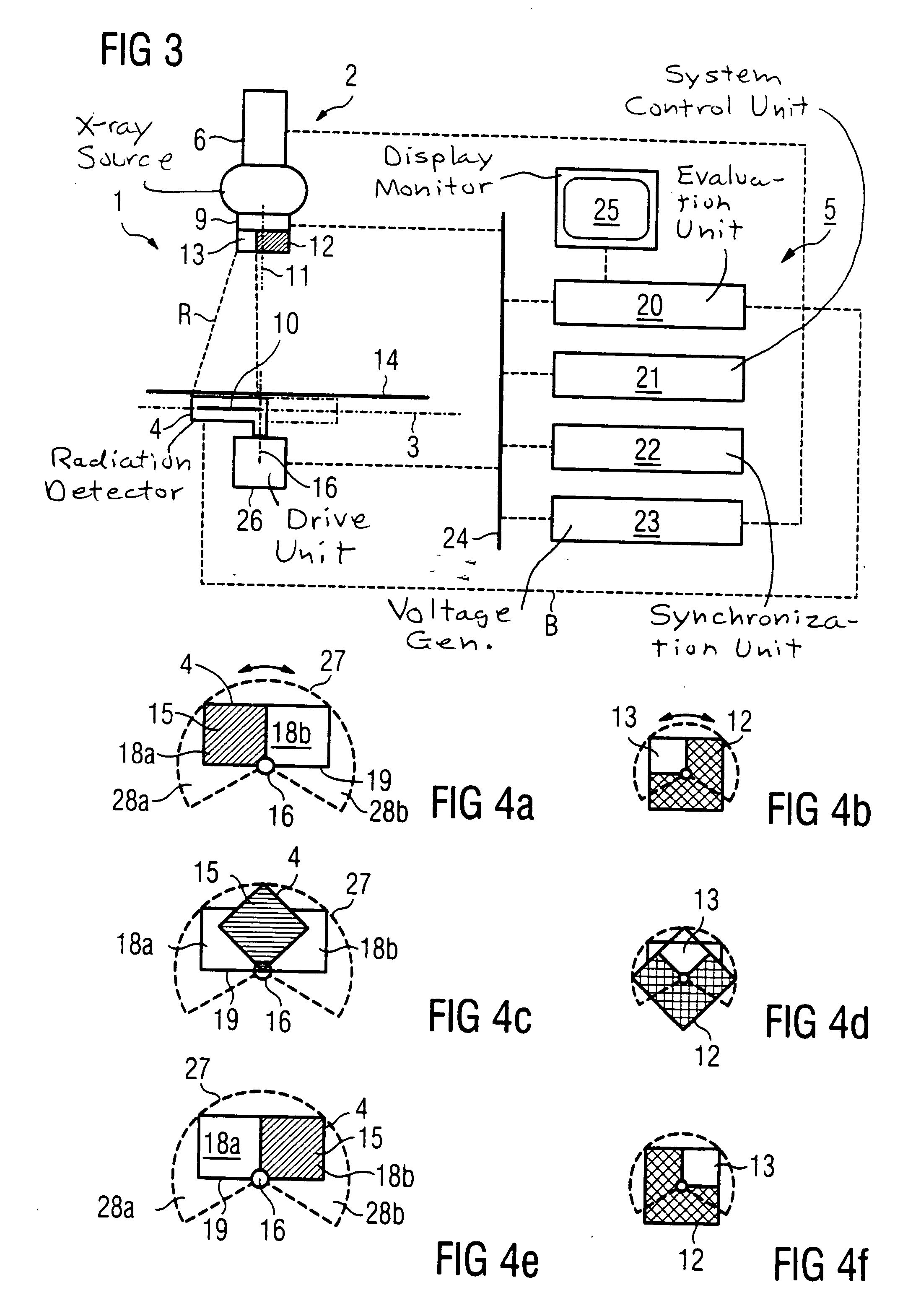
[0032]FIG. 1 shows an X-ray apparatus 1 having an exposure unit 2, an X-ray detector 4 situated in an exposure plane 3, and a control and evaluation system 5.

[0033] The exposure unit 2 includes an X-ray source 6 for producing a beam of X-ray radiation R. In the direction 7 of the radiation, a diaphragm system 9 is connected downstream from the X-ray source 6. In the diaphragm system 9, a portion of the X-ray radiation R is selected that strikes an exposure plane 3 within a predetermined surface segment 10. As a result, the surface segment 10 is exposed by the X-ray radiation R. The remaining X-ray radiation R produced by X-ray source 6 is absorbed by the diaphragm system 9 in order to avoid undesirable scatter radiation. The area of exposure plane 3 situated outside surface segment 10 is thus largely blocked from the X-ray radiation R.

[0034] The diaphragm system 9 includes a diaphragm 12 that can be rotated around an axis of rotation 11, and that has a diaphragm aperture 13 that i...


PUM

PropertyMeasurementUnit
angle of rotationaaaaaaaaaa
sizeaaaaaaaaaa
digital imaging techniquesaaaaaaaaaa

Abstract

An economical X-ray apparatus that allows a rapid exposure of comparatively large-format digital X-ray images has an exposure unit, with which a predetermined surface segment of an exposure plane can be exposed with X-ray radiation, and a digital X-ray detector that is moved in the exposure plane, with the X-ray detector being continuously periodically driven.

Description

BACKGROUND OF THE INVENTION [0001] 1. Field of the Invention [0002] The present invention relates to an X-ray apparatus of the type having an exposure unit by means of which a predetermined surface segment of an exposure plane can be exposed using X-ray radiation, and having a digital X-ray detector that can be moved in the exposure plane. [0003] 2. Description of the Prior Art [0004] For years, most of the imaging examination methods used in medical technology have been based on X-ray images. In recent years, digital imaging techniques have increasingly become established, in place of conventional radiography based on photographic films. These digital techniques have the considerable advantage that the development of film, which is time-consuming, is not required. Rather, the image preparation takes place by means of electronic image processing. The image is therefore available immediately after the exposure. In addition, digital X-ray exposure techniques offer the advantage of imp...

Claims


Application Information

Patent Timeline
Patent Type & Authority Applications(United States)
IPC IPC(8): A61B6/03
CPCA61B6/032
Inventor MASCHKE, MICHAEL
Owner SIEMENS AG
Why Eureka
Eureka Blog
Learn More