Sheet feeding apparatus and image forming apparatus

a technology of feeding apparatus and image forming apparatus, which is applied in the direction of thin material processing, instruments, and article separation, etc., can solve the problems of generating noise, deteriorating the noise level of the printer, and the technique does not address the problem of trailing edge jumping, etc., and achieves the effect of reducing noise and silent operation

Inactive Publication Date: 2005-01-06
CANON KK
View PDF18 Cites 10 Cited by
  • Summary
  • Abstract
  • Description
  • Claims
  • Application Information

AI Technical Summary

Benefits of technology

[0017] The present invention has been devised in order to solve the above-mentioned problems, and it is an object of the present invention to realize a sheet feeding apparatus with reduced noise and provide an image forming apparatus capable of silent operation.

Problems solved by technology

However, the conventional sheet feeding apparatus disclosed in Japanese Patent Application Laid-Open No. 08-157110 has a problem in that a trailing edge of a sheet that is fed after being separated jumps as the sheet passes through the separation pad, thus generating noise.
However, the technique disclosed in the laid-open patent application only addresses the problem of trailing edge jumping sound that is caused as the trailing edge of the separated sheet jumps after passing through a press-contact portion between the sheet feeding roller and the separation pad.
The technique does not address the problem of trailing edge jumping sound that is caused when the trailing edge of the separated sheet moves away from a sheet stacking portion.
In particular, this trailing edge jumping sound becomes more noticeable with a stiff sheet such as thick sheet, causing deterioration in the noise level of the printer 1.

Method used


Image

  • Sheet feeding apparatus and image forming apparatus
  • Sheet feeding apparatus and image forming apparatus
  • Sheet feeding apparatus and image forming apparatus

Examples


first embodiment

[0036] First Embodiment

[0037] A first embodiment of a sheet feeding apparatus of the present invention will be explained below with a laser beam printer, which is an image forming apparatus adopting an electrophotographic system, as an example.

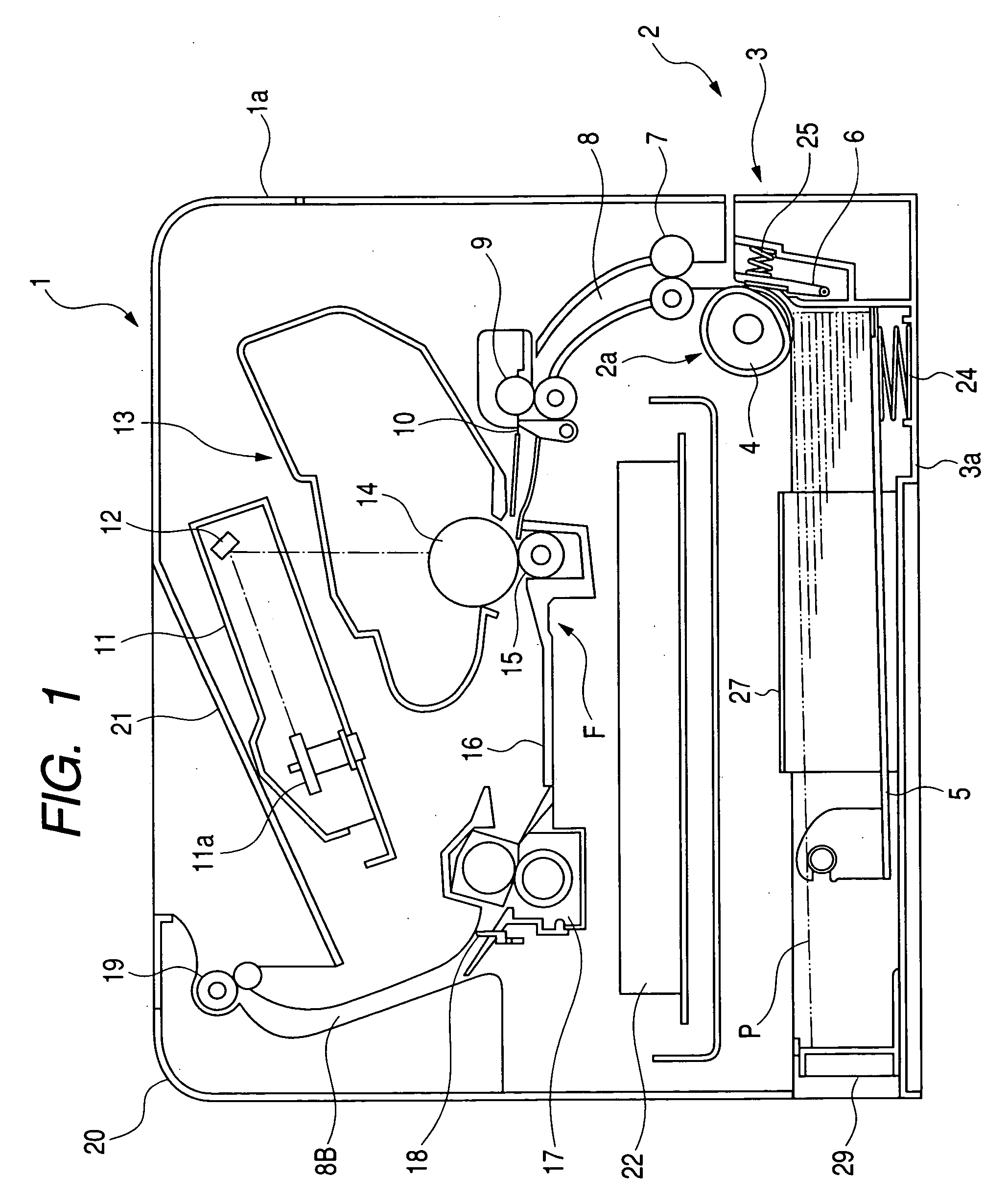
[0038]FIG. 1 is a sectional view of a laser beam printer (hereinafter referred to as printer) 1. FIG. 2 is a sectional view of a sheet feeding apparatus mounted on this printer 1. FIG. 3 is a perspective view of a sheet feeding cassette that is mounted on the sheet feeding apparatus shown in FIG. 1. A structure of the printer 1 will be explained with reference to these figures.

[0039] (Image Forming Portion)

[0040] In FIG. 1, an image forming portion F includes: a process cartridge 13 that is constituted by a photosensitive member 14, and a developing device, a cleaner, a charging roller, and the like, which are not shown in the figure; a transferring roller 15 that transfers a visualized image on the photosensitive member 14 onto a sheet P; ...

second embodiment

[0071] Second Embodiment

[0072] Next, a second embodiment of the sheet feeding apparatus in accordance with the present invention will be explained with reference to FIGS. 8 and 9. Note that only structures and operations different from those in the first embodiment will be explained. The other structures and operations are the same as those in the first embodiment.

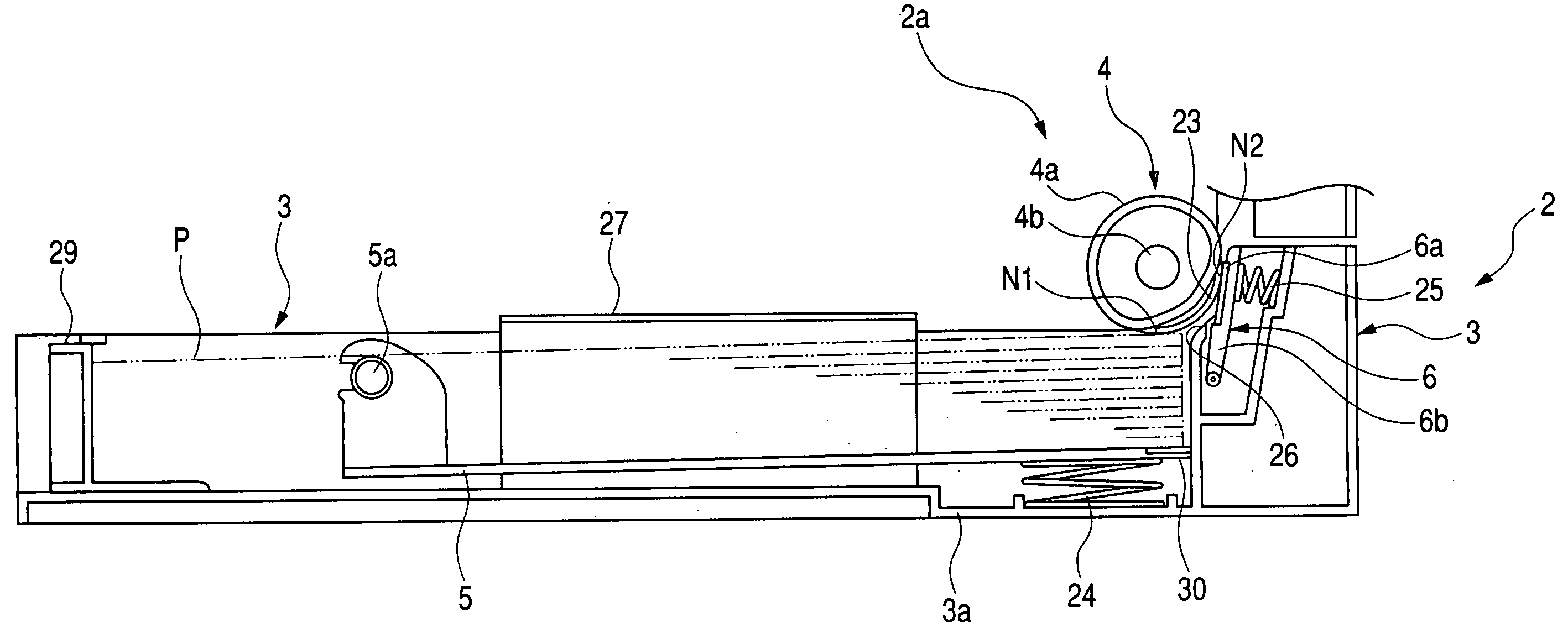
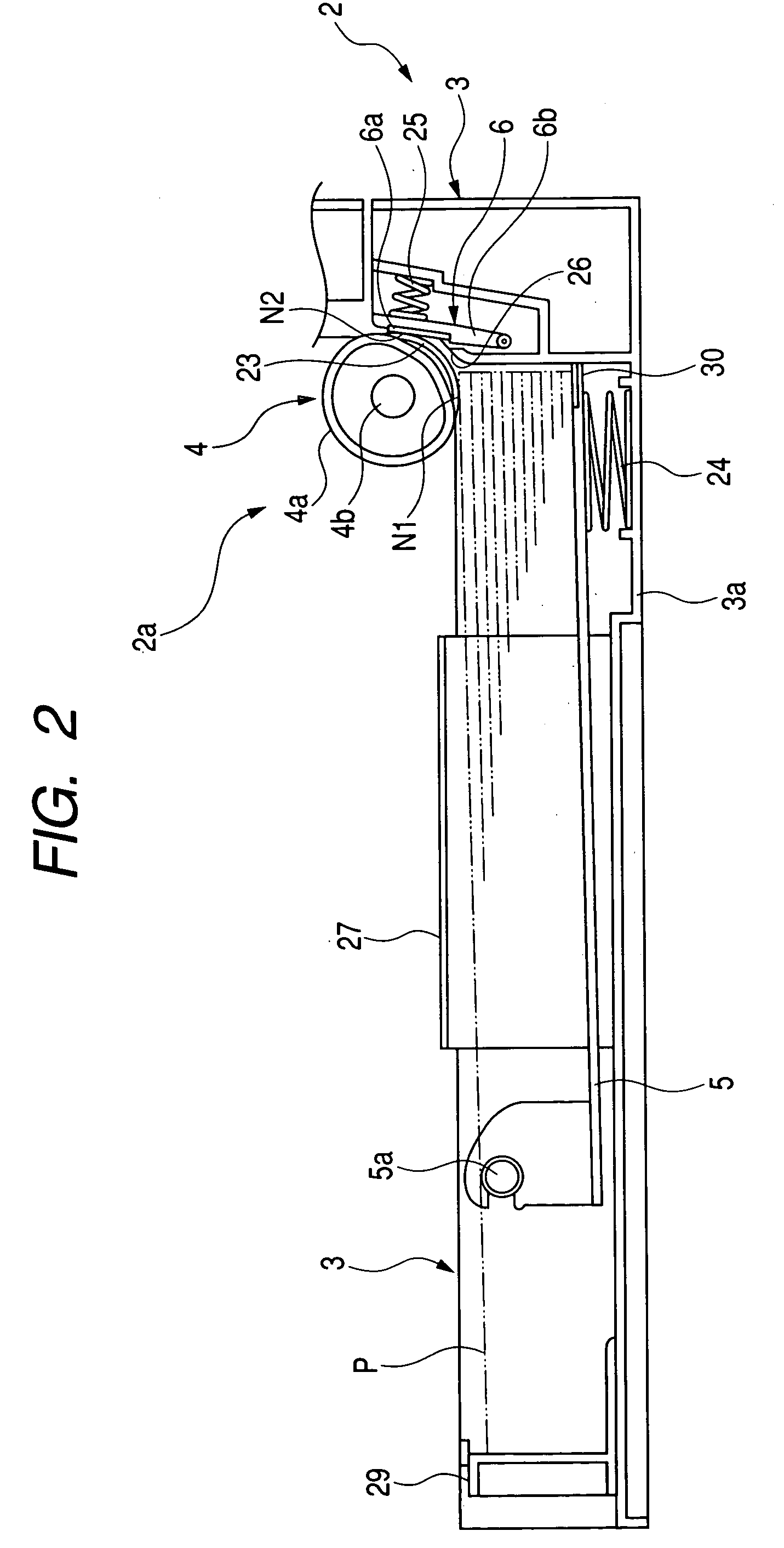
[0073]FIG. 8 is a sectional view of a sheet feeding apparatus 2 in accordance with the second embodiment. FIG. 9 is a perspective view of a sheet feeding cassette 3 that is mounted on this sheet feeding apparatus.

[0074] In the sheet feeding apparatus 2, the inclined guide surface 26, which is provided between the pushing portion N1 where the sheets P are pushed against the sheet feeding roller 4 by the pressure plate 5 and the abutting portion N2 where the sheet feeding roller 4 and the separation pad 6 come into abutment against each other, and which guides the sheets P delivered by the sheet feeding roller 4 toward the...

third embodiment

[0077] Third Embodiment

[0078] Next, a third embodiment of the sheet feeding apparatus in accordance with the present invention will be explained. FIG. 10 is a main part sectional view of the sheet feeding apparatus in accordance with the third embodiment. Only structures and operations different from those of the first and the second embodiments will be described. The other structures and operations are the same as those in the first and the second embodiments.

[0079] In the sheet feeding apparatus 2, the sheet guide surface 26 is formed in an arc shape with an inner diameter surface thereof serving as a sheet guide. The sheet guide surface 26 is provided between the pushing portion N1, where the sheets P are pushed against the sheet feeding roller 4 by the pressure plate 5, and the abutting portion N2, where the sheet feeding roller 4 and the separation pad 6 come into abutment against each other, and guides the sheets P delivered by the sheet feeding roller 4 toward the abutting p...


PUM


Abstract

A sheet feeding apparatus includes: a sheet containing device for housing sheets; a sheet feeding roller that feed the sheets contained in the sheet containing device; a pushing member for pushing the sheets contained in the sheet containing device against the sheet feeding roller; a separation pad which is provided so as to be capable of abutting against the sheet feeding roller and separates the sheets one by one as the sheets are fed by the sheet feeding roller and the pushing member; and a sheet guide portion arranged between a pushing portion where the sheets are pushed against the sheet feeding roller by the pushing member and an abutting portion where the sheet feeding roller and the separation pad come into abutment against each other. As a result, a sheet feeding apparatus with reduced noise can be realized. In addition, an image forming apparatus with silent operation can be realized by using the sheet feeding apparatus.

Description

[0001] This application claims priority from Japanese Patent Application No. 2003-190395 filed on Jul. 2, 2003, which is hereby incorporated by reference. BACKGROUND OF THE INVENTION [0002] 1. Field of the Invention [0003] The present invention relates to a sheet feeding apparatus that is provided in an image forming apparatus for forming an image on a recording medium such as an electrophotographic copying machine, a printer, a word processor, or a facsimile apparatus. [0004] 2. Related Background Art [0005] A sheet feeding apparatus for automatically feeding a recording medium (hereinafter referred to as sheet) to an image forming portion is mounted on an image forming apparatus. FIGS. 13 to 16 show an example of a conventional image forming apparatus and a sheet feeding apparatus mounted on this image forming apparatus. [0006]FIG. 13 is a schematic sectional view of a laser beam printer (hereinafter referred to as printer) 1 that is a conventional image forming apparatus. FIG. 14...

Claims


Application Information

Patent Timeline
Patent Type & Authority Applications(United States)
IPC IPC(8): B65H1/04B65H3/52G03G15/00B65H3/68
CPCB65H1/04B65H2405/113B65H3/5223B65H1/266G03G15/6558G03G15/6564
Inventor YUZA, AKIRAMATSUO, YOSHIHIRO
Owner CANON KK
Why Eureka
Try Eureka