
Scanning beam optical imaging system for macroscopic imaging of an object

Inactive Publication Date: 2004-12-30
BIOMEDICAL PHOOMETRICS
View PDF5 Cites 50 Cited by
  • Summary
  • Abstract
  • Description
  • Claims
  • Application Information

AI Technical Summary

Benefits of technology

[0011] It is a further object of this invention to provide a liquid-immersion laser scan lens with spring-loaded bottom elements to prevent damage on contact between the lens and the sample.
[0016] It is a further object of this invention to provide a method of scanning macroscopic specimens that uses a liquid-immersion laser scan lens to provide increased resolution and laser light intensity at the focal point.

Problems solved by technology

This is very time consuming, and considerable care must be taken to match up the sides of the small images.

Method used


Image

  • Scanning beam optical imaging system for macroscopic imaging of an object
  • Scanning beam optical imaging system for macroscopic imaging of an object
  • Scanning beam optical imaging system for macroscopic imaging of an object

Examples


Embodiment Construction

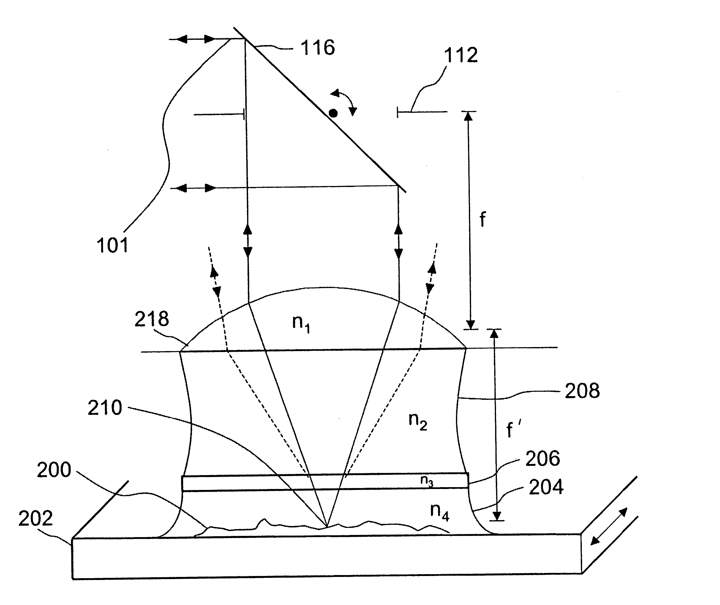
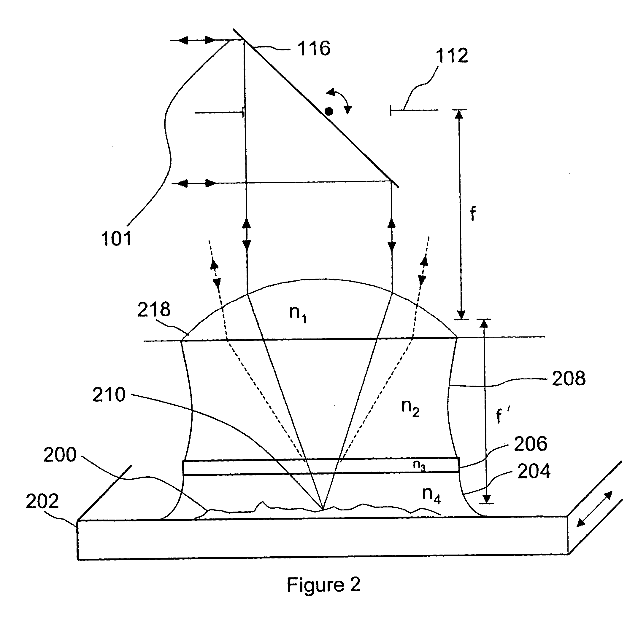
[0036] Assuming diffraction-limited performance in a laser focusing lens (whether it is a simple molded lens with one or two aspheric surfaces, a more complicated lens like a microscope objective, or a laser scan lens), the size of the focused spot depends on the laser wavelength and the numerical aperture (NA) of the lens. The Full Width Half Maximum (FWHM) of the illumination Point Spread Function of the focused laser spot is given by.sup.1 (for unpolarized light):

W.sub.x=W.sub.y=0.51.lambda. / (n sin .alpha.) (1)

and W.sub.z=0.44.lambda. / (n sin.sup.2(.alpha. / 2)) (2)

[0037] where n is the index of refraction of the immersion medium, and .alpha. is the semi-aperture angle of the scan lens (NA=n sin.alpha.). The z direction is the axial direction. These formulas are changed only slightly for polarized light.

[0038] When the word "object" is used in the present application, it includes any subject that is used with an optical imaging system or with a liquid immersion scan lens including, ...


PUM


Abstract

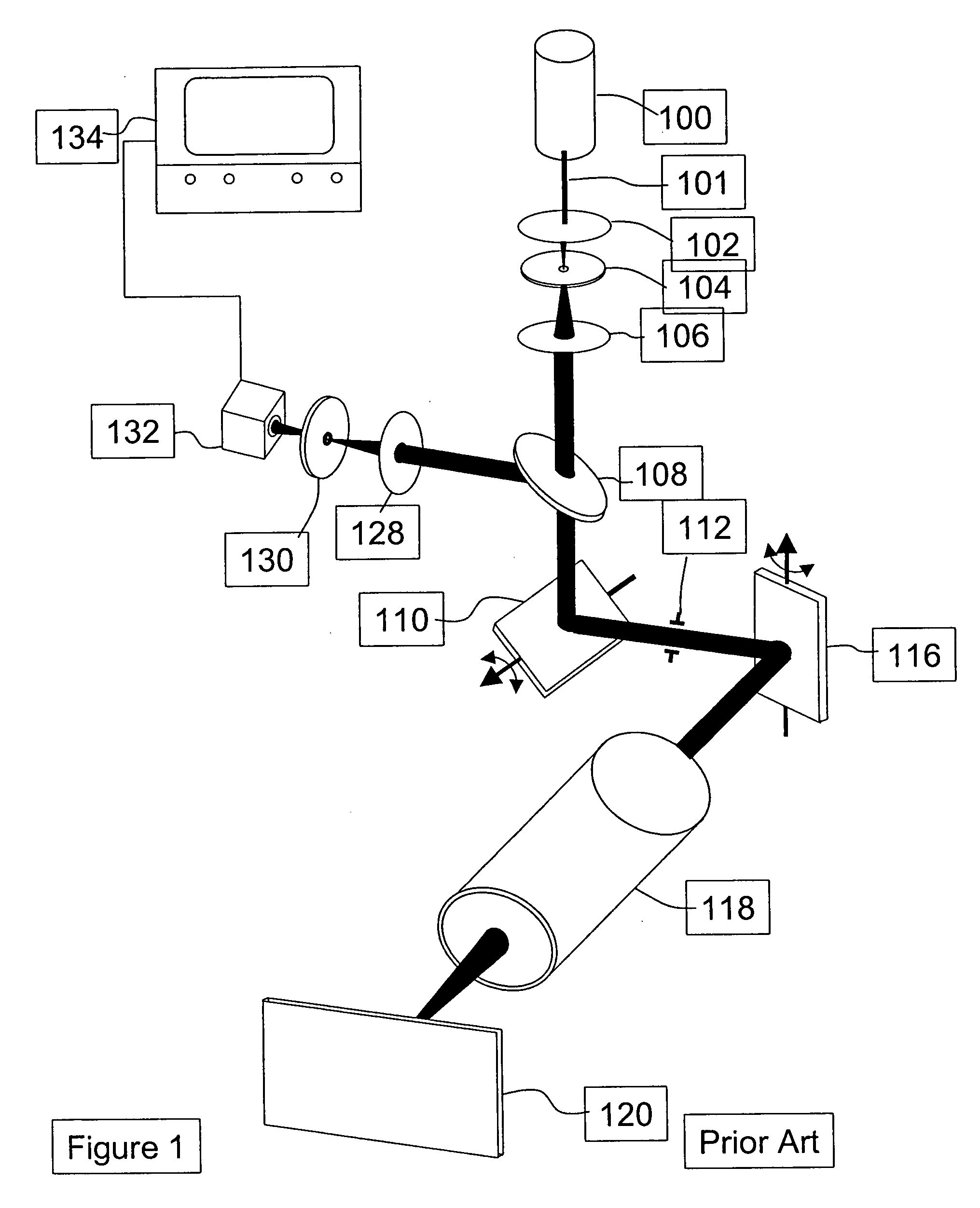
A new high resolution confocal and non-confocal scanning laser macroscope is disclosed which images macroscopic specimens in reflected light, transmitted light, fluorescence, photoluminescence and multi-photon fluorescence. The optical arrangement of a scanning laser macroscope has been altered to include a liquid-immersion laser scan lens, providing higher numerical aperture and higher resolution; and higher intensity at the focal spot, which makes the macroscope particularly well suited for multiphoton imaging. Several applications of the imaging system are described. A liquid-immersion laser scan lens with spring-loaded bottom element and method for containing the immersion liquid are also disclosed.

Description

[0001] 1. Field of Invention[0002] This invention relates to a scanning beam optical imaging system for macroscopic imaging of an object. More particularly, this invention relates to the fields of confocal and non-confocal imaging of microscopic and macroscopic objects with emphasis on scanning-beam imaging systems using reflected light, transmitted light, fluorescence and photoluminescence as contrast mechanisms, including multi-photon fluorescence imaging and spectrally-resolved fluorescence imaging.[0003] 2. Description of the Prior Art[0004] For confocal and non-confocal imaging, the most important characteristics of a laser scan lens are its external entrance pupil (at which position a scanner can be placed), and its wide field of view. In contrast, a microscope objective has an entrance pupil positioned at the entrance to or inside the lens barrel, and intermediate optics must be used to translate the scanning beam from the scanner to the position of the entrance pupil. In add...

Claims


Application Information

Patent Timeline
IPC IPC(8): G02B21/00
CPCG02B21/002G02B21/0024
Inventor DIXON, ARTHUR E.DAMASKINOS, SAVVAS
Owner BIOMEDICAL PHOOMETRICS
Learn More