Video with Map Overlay
a technology of video image and overlay, applied in the field of video image with overlay, can solve the problem that the information displayed on the video image may not have enough reference points on the image to easily direct ground officers
- Summary
- Abstract
- Description
- Claims
- Application Information
AI Technical Summary
Benefits of technology
Problems solved by technology
Method used
Image

Examples
embodiment 100
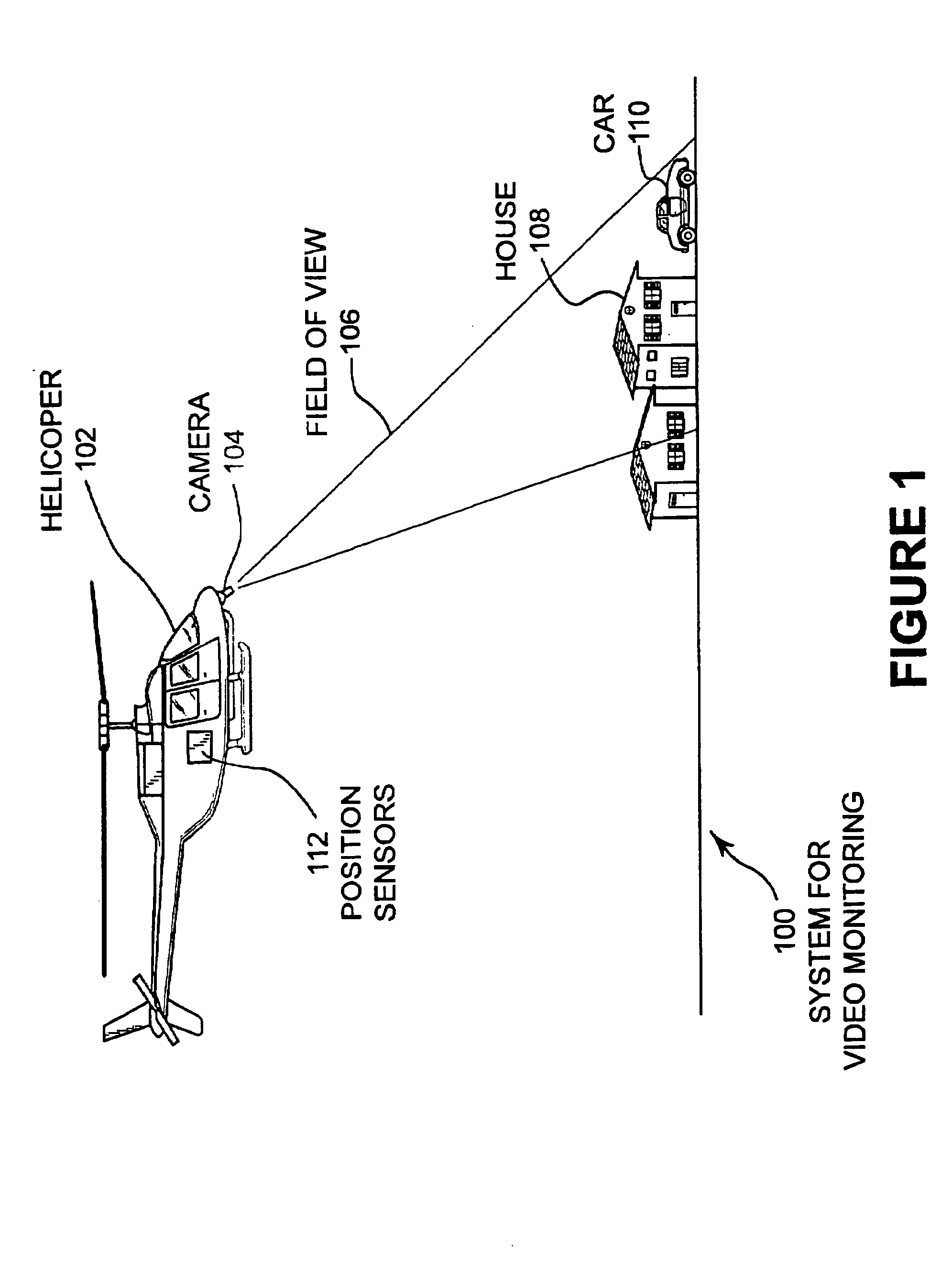
[0029] FIG. 1 illustrates the present invention showing a system for video monitoring. A helicopter 102 has a mounted and gimbaled camera 104. The camera 104 has a field of view 106 that covers a house 108 and a car 110. The helicopter 102 is fitted with position sensors 112.
[0030] The helicopter 102 may be any type of aircraft, land vehicle, or watercraft. In this specification, a helicopter is used as an example vehicle to best show the various elements of the invention. Other embodiments may use airplanes, balloons, remotely controlled aircraft, cars, trucks, military armored vehicles, motorcycles, bicycles, amphibious vehicles, boats, ships, submarines, spacecraft, satellites, or any other mobile device. In some cases, the vehicle may be a pedestrian.
[0031] The camera 104 may be fixed mounted to the helicopter 102 or may be movable and controllable. For applications such as a helicopter, airplane, or other aircraft, a stabilized camera mount may be desired. Such a camera mount m...
embodiment 200
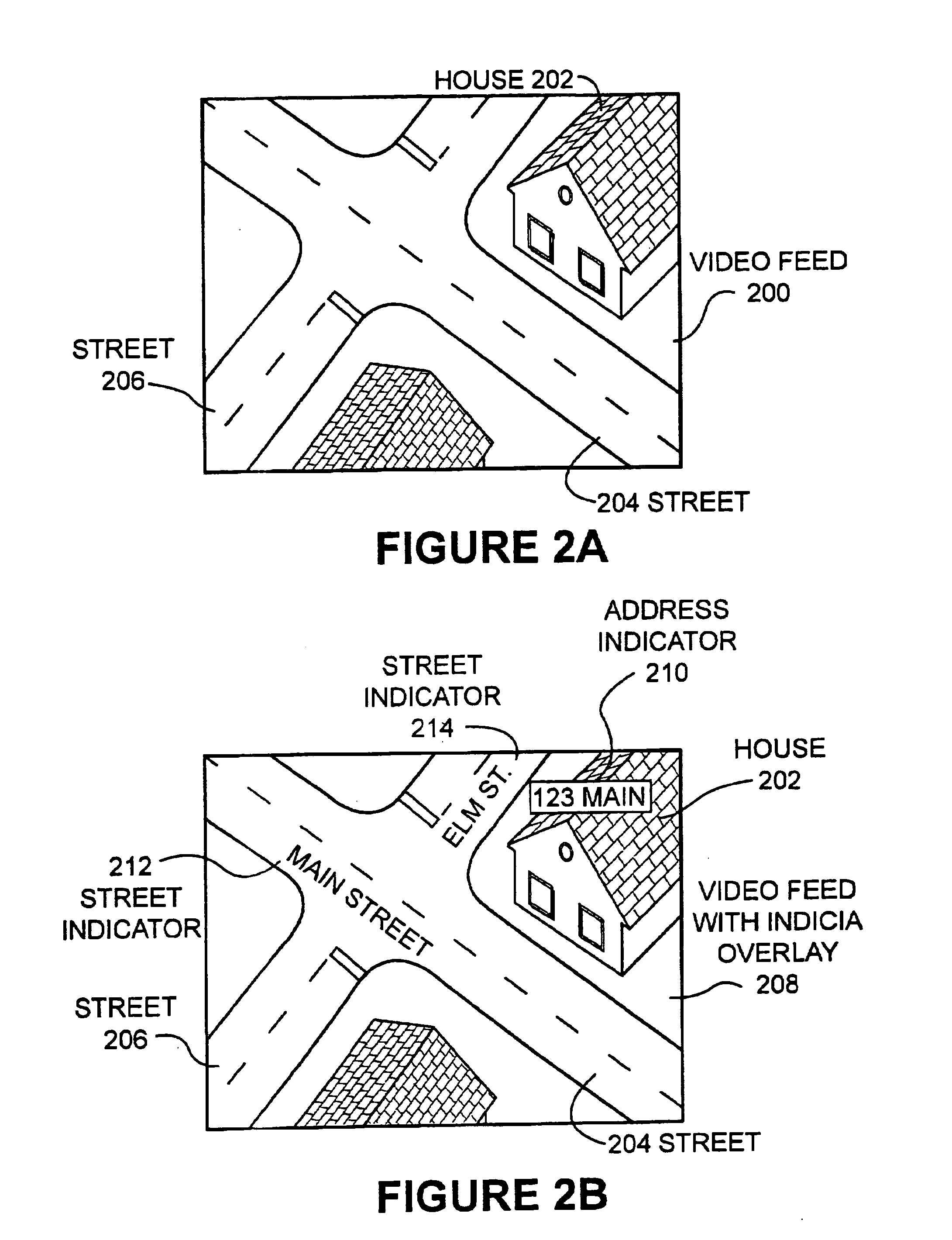
[0036] FIG. 2A illustrates a video feed without overlay indicia. The video feed 200 shows a house 202 and streets 204 and 206.
[0037] The embodiment 200 may be an example of a video image taken by a police helicopter during a search for a suspect. A particular difficulty with such a video feed is that the video operator is zoomed so far in that landmarks may be difficult to determine. Because there are few landmarks, it may be difficult for someone to direct police officers to the scene or location of a suspect.
embodiment 208
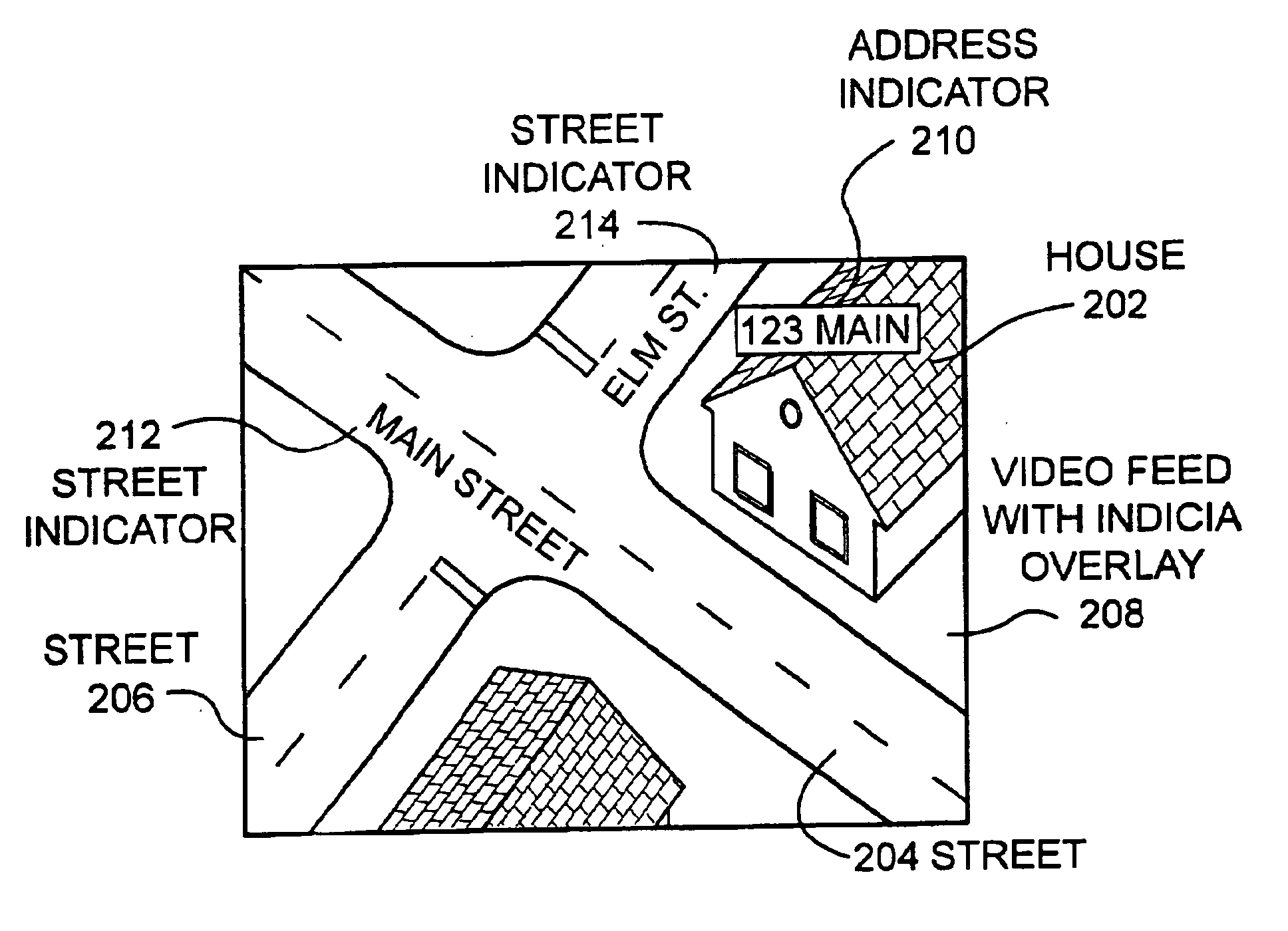
[0038] FIG. 2B illustrates the video feed of FIG. 2A with an indicia overlay. The house 202 may be overlaid with an address indicator 210. Similarly, streets 204 and 206 may have street indicators 212 and 214 overlaid.
[0039] In the present embodiment of a police helicopter video, the video screen with the indicia give much more useful and important information to the dispatcher who is directing the movement of officers on the scene. For example, in embodiment 200 of the pure video feed, it would be difficult to determine which intersection or which house is in the field of view, especially when the area is a large subdivision with many similar homes and streets. In the embodiment 208, the address of the home in the image is given, along with the cross streets. This information could be extremely useful in directing additional officers to the scene.
[0040] Many types of indicia can be overlaid on top of the video feed. For example, topographic lines, geographic features, location and ...
PUM
 Abstract
Description
Claims
Application Information
 - R&D
- Intellectual Property
- Life Sciences
- Materials
- Tech Scout
- Unparalleled Data Quality
- Higher Quality Content
- 60% Fewer Hallucinations
Browse by: Latest US Patents, China's latest patents, Technical Efficacy Thesaurus, Application Domain, Technology Topic, Popular Technical Reports.
© 2025 PatSnap. All rights reserved.Legal|Privacy policy|Modern Slavery Act Transparency Statement|Sitemap|About US| Contact US: help@patsnap.com