
Stainless steel tubing/frit with sintered inorganic particle, the chromatography comprising it, and their manufacturing method

a technology of inorganic particle and steel tubing, which is applied in the direction of filtration separation, separation processes, instruments, etc., can solve the problems of inability to remove fibrils, increase the cost and inconvenience of use, and reduce the efficiency of columns, so as to achieve simple design convenience of column production and low cost

Inactive Publication Date: 2004-12-02
CHEONG WON JO +1
View PDF23 Cites 11 Cited by
  • Summary
  • Abstract
  • Description
  • Claims
  • Application Information

AI Technical Summary

Benefits of technology

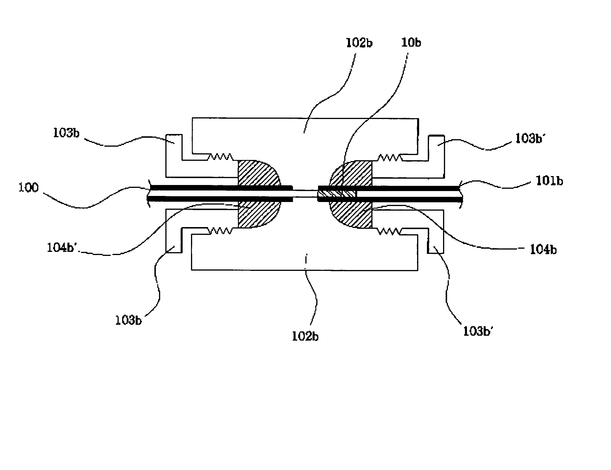
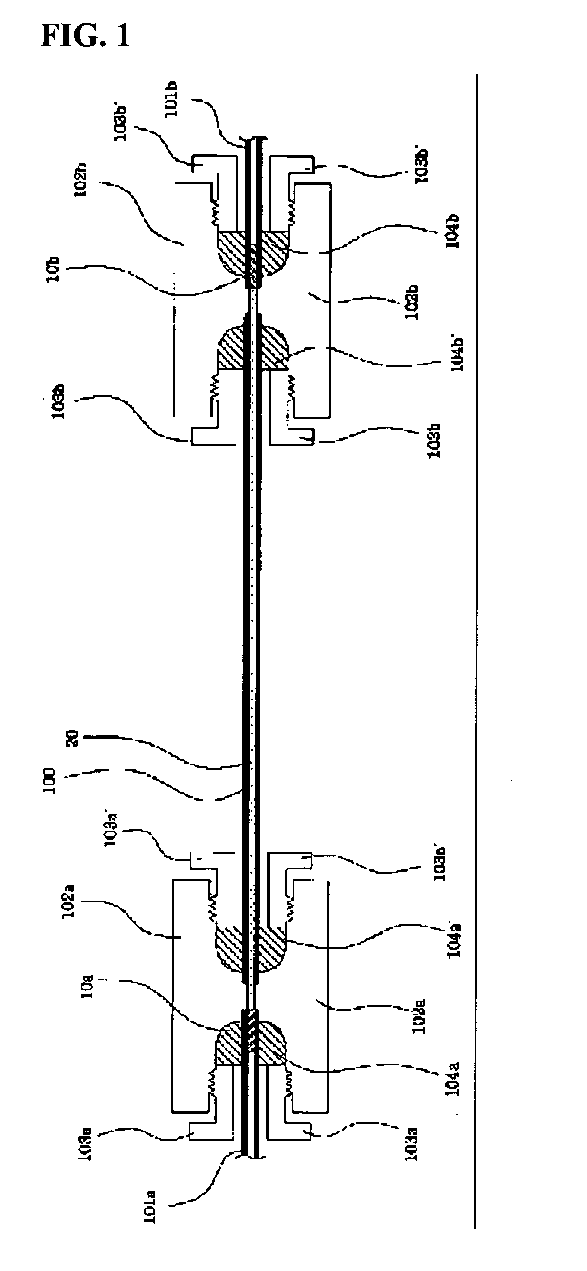
[0023] The purpose of this invention is to offer a tubing / frit and a chromatographic column installed with the tubing / frit's with the advantages of simple design convenience of column production, and low cost.

Problems solved by technology

In all cases, frits are installed inside the column main body, and the frits cannot be removed without disassembling the column.
Besides, perturbation of mobile phase flow and consequent reduction of column efficiency can occur if the frit diameter is very larger than the column I.D. or the I.D. of connection tubing.
Adopting complicated designs for the frit structure to solve such problems yields cost increase and inconvenience of use.
Furthermore, it is very difficult to make separate miniaturized frits for microcolumns with I.D. of 0.5 mm or less whose relative importance has been rapidly increased, and, actually, microcolumns with such frits are not commercially available.
In this case, column repacking is impossible, and the column lifetime ends when the frit is clogged or a crack or void volume develops in the column.
First, in the case of permanent end frits only at the column inlet and outlet, cracks in the packing structure are sometimes observed after formation of end frits, and the column efficiency is degraded.
Furthermore, if frit clogging happens in the course of forming the inlet frit after packing the column with the stationary phase powders, then the whole column finishes its lifetime without being used at all.
First of all, it is difficult to make a monolith without a void volume in a rigid conventional stainless steel column with I.D. of 1-5 mm, thus formation of monolith is confined in a heat-shrinkable polymer tubing.
Such manufacturing technique seems to suffer from low reproducibility of production.
A lot of care should be taken in end fitting treatment of the polymer tubing of low strength, and such products will have endurance problem.
Furthermore, production reproducibility of silica capillary monoliths is not well known, and it is improper to apply to a pilot or industrial scale.
There has been no frit technique so far to make permanent frits not in the column main body but in the connection tubing between the column and other devices such as an injector or detector.
The problem is, however, it is difficult to make a permanent frit combined to the inner surface of the connection tubing end with endurance over high pressure and mobile phase flow on packing or operating the column.

Method used


Image

  • Stainless steel tubing/frit with sintered inorganic particle, the chromatography comprising it, and their manufacturing method
  • Stainless steel tubing/frit with sintered inorganic particle, the chromatography comprising it, and their manufacturing method
  • Stainless steel tubing/frit with sintered inorganic particle, the chromatography comprising it, and their manufacturing method

Examples


example 2

[0086] Production of Metal Tubing / Frit's with Chemically and Thermally Sintered Silica Frits II: 0.8 mm I.D.

[0087] One gram spherical porous 10.mu., 100 .ANG..degree. silica particles are dispersed in a 20 mL 5 wt % KOH solution, and the dispersion is spread over a hard and flat polymer surface as a thin layer, and dried at 50-60.degree. C. under a glass board to protect the dispersion layer from falling dirts. The dried layer is scraped with a polymer scoop and rubbed gently with a round pestle into fine powders.

[0088] The above silica powders are then uniformly spread on a flat polymer surface with a depth of 2 mm or so. Metal tubings of 5 cm.times.0.8 mm.times.1.6 mm (length.times.I.D..times.O.D.) are located vertically over the fine powders, and are allowed to hit the surface gently and at various spots 100 times to get the particles in with a depth of 2.about.3 mm. The outer wall of the tubing is cleaned with a soft tissue.

[0089] The tubing with the silica powders filled at the...

example 3

[0092] Production of Metal Tubing / Frit's with Chemically and Thermally Sintered Silica Frits III: 0.25 mm I.D.

[0093] One gram spherical porous 5.mu., 100 .ANG..degree. silica particles are dispersed in a 10 mL 10 wt % NaOH solution, and the dispersion is spread over a hard and flat polymer surface as a thin layer, and dried at room temperature under a glass board to protect the dispersion layer from falling dirts. The dried layer is scraped with a polymer scoop and rubbed gently with a round pestle into fine powders.

[0094] The above silica powders are then uniformly spread on a flat polymer surface with a depth of 2 mm or so, and metal tubings of 5 cm.times.0.25 mm.times.1.6 mm (length.times.I.D..times.O.D.) are located vertically over the fine powders, and are allowed to hit the surface gently and at various spots 100 times to get the particles in with a depth of 2.about.3 mm. The outer wall of the tubing is cleaned with a soft tissue.

[0095] The tubing with the silica powders fille...

example 4

[0097] Production of Metal Tubing / Frit's with Sintered Alumina Frits.

[0098] One gram spherical porous 5.mu., alumina particles with a specific surface area of 70 m.sup.2 / g are dispersed in a 5 mL 10 wt % NaOH solution, and the dispersion is spread over a hard and flat polymer surface as a thin layer, and dried at room temperature under a glass board to protect the dispersion layer from falling dirts. The dried layer is scraped with a polymer scoop and rubbed gently with a round pestle into fine powders.

[0099] The above alumina powders are then uniformly spread on a flat polymer surface with a depth of 2 mm or so, and stainless steel tubings of 5 cm.times.0.25 mm.times.1.6 mm (length.times.I.D..times.O.D.) are located vertically over the fine powders, and are allowed to hit the surface gently and at various spots 100 times to get the alumina powders in with a depth of 2.about.3 mm. The outer wall of the tubing is cleaned with a soft tissue.

[0100] The tubing with the alumina powders f...


PUM

PropertyMeasurementUnit
Pore sizeaaaaaaaaaa
Concentrationaaaaaaaaaa
Heightaaaaaaaaaa

Abstract

This invention is about metal tubing / frit applicable in liquid chromatography and a chromatography column manufactured by using the same. In detail, this invention is about manufacturing the metal tubing / frit by treating a powdered inorganic oxide such as silica, alumina, zirconia, and titania with a strong base, drying it with some humidity included, scrubbing it into powders, putting it in the tip of a chromatographic metal tubing at a proper depth, and by sintering the powders to form a durable sintered frit on the inner wall. This invention is also about a liquid chromatographic column manufactured by installing the metal tubing / frit's with a sintered end frit at the column inlet and outlet unions and by placing the cylinder-like column main body tubing packed with a stationary phase between the unions. The metal tubing / frit manufactured according to the description above is not placed inside the column as in the conventional column design, thus it is easily replaced and fixed without disassembling the column, and the column of this design can displace the conventional microcolumn of complicated production process and high cost.

Description

[0001] This invention is about metal tubing / frit's and columns manufactured by using the same for liquid chromatography. First, this invention is about powders with tiny amount of humidity manufactured by treating inorganic oxide powders such as silica, alumina, titania, and zirconia with a strong base followed by drying.[0002] This invention is also about manufacturing metal tubing / frit's by putting the above mentioned powders into the tip of metal tubing designed for column chromatography at a proper height and by sintering them into a solid frit.[0003] This invention is also about a liquid chromatographic column manufactured by installing the above mentioned metal tubing / frit's with a sintered end frit at the column inlet and outlet unions and by placing the cylinder-like column main body tubing packed with a stationary phase between the unions.[0004] The liquid chromatography column is composed of three major parts, that is, a column body tubing, end-fitting blocks at both ends ...

Claims


Application Information

Patent Timeline
IPC IPC(8): G01N30/56B01D15/22C01B13/14C01G1/02G01N30/60
CPCB01D15/22C01G1/02C01P2002/87C01P2004/03G01N30/6004G01N30/603G01N30/6039G01N2030/562G01N30/56
Inventor CHEONG, WON JO
Owner CHEONG WON JO
Learn More