
Device for combining two fluid streams

Inactive Publication Date: 2004-11-25
OAKLAND UNIVESITY
View PDF2 Cites 38 Cited by
  • Summary
  • Abstract
  • Description
  • Claims
  • Application Information

AI Technical Summary

Benefits of technology

[0032] The object of the present invention is to provide a device which introduces a segment of fluid containing sample components into a flow of pure gas. The preferred device which injects the sample components as a short pulse, maximizes the amount of sample injected, which minimizes the disturbances to all of the gas flows (i.e., the sample gas flow, the pure gas flow, and the flow to the analytical device), and which is capable of consistently repeating this process at a frequency of approximately 1 Hz. It is further an object of the present invention to provide a device which is relatively low in cost and reliable. These and other objects will become increasingly apparent by reference to the following description and the drawings.

Problems solved by technology

This modulator was effective at demonstrating the resolving power of GC.times.GC separations but not sufficiently robust for routine use.
The main disadvantages are that liquid cryogen is required and a system capable of delivering liquid cryogen into the oven of the gas chromatograph must be engineered.
The direct diverting approach reduces the sensitivity of the analysis because only a small amount (<10%) of each component is transferred from the primary column to the secondary column.
There are three drawbacks to the differential flow modulation approach.
First, high secondary flows are required to produce high peak capacity.
However, the requirement of high flow and long columns limits the use of micro-bore secondary columns (i.e., columns with internal diameters less than 0.15 mm) because excessively high head pressures would be required.
Temperature limitations are a second drawback of differential flow modulation.
Such valves have internal actuating mechanisms that are damaged at temperatures greater than 200.degree. C.
This reduces the range of samples that can be analyzed.
This increases the temperature limit of the technique, but the current maximum temperature of a published diaphragm valve separation is 240.degree. C.
Pressure and flow fluctuations produced by valve switching are a third problem associated with diaphragm valve modulation.
However, it is possible that fluctuations would lead to degraded resolution if short secondary columns were used.
This limits the sensitivity of component detection and limits the precision component transfer if the composition of FS changes with time.
Such valves have upper temperature limits of 200.degree. C.
This reduces the range of samples that can be analyzed with such a device.
Cost and Availability: The diaphragm valves used for this type of sampling often cost near $1000.
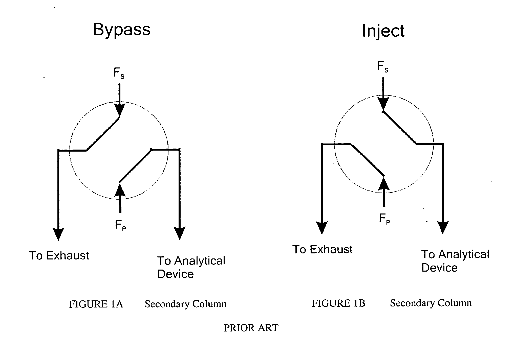
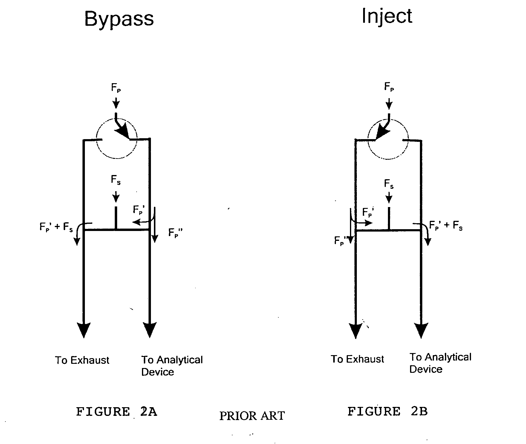
Unlike the multi-port valve, sample dilution can be significant (and undesirable) if F.sub.P' is not substantially smaller than F.sub.S.
However, such devices must often be constructed by the user.
Such valves have upper temperature limits of 200.degree. C.
This reduces the range of samples that can be analyzed with such a device.
Cost and Availability: The diaphragm valves used for this type of sampling often cost near $1000.

Method used


Image

  • Device for combining two fluid streams
  • Device for combining two fluid streams
  • Device for combining two fluid streams

Examples


example 1

[0073] General Setup

[0074] A schematic of the GC.times.2GC system is shown in FIG. 9, which is enclosed in an oven, was used. A Perkin-Elmer (Norwalk, Conn., USA) Autosystem XL gas chromatograph with electronic pneumatics and dual flame-ionization detectors (FIDs) was used as the experimental platform. Ultra-high purity hydrogen was used as the carrier gas in the primary and secondary columns. Neat mixtures were injected into the primary column through a split inlet (30:1 split ratio). The flow exiting the switching device was divided between two secondary columns with a tee union. Effluent from each secondary column was passed through a flame-ionization detector (FID). The 100 nF filtering capacitor on each FID electrometer was replaced by an 8 nF capacitor. The signals from the detectors were monitored at 200 Hz by a personal computer equipped with a data acquisition board and custom software. The capillary columns used in these studies can be purchased from Agilent Technologies (...

example 2

[0091] The goal of this Example was to determine the influence of experimental parameters, such as the primary flow rate, secondary flow rate, and device dimensions, on the performance of the flow-switching modulator. These parameters were investigated to determine how they influence the width and shape of modulated peaks. An apparatus was constructed that allows the primary and secondary flow rates to be controlled independently with high precision. In addition, the apparatus enabled the flow-switching device to be directly compared to multi-port valve modulation.

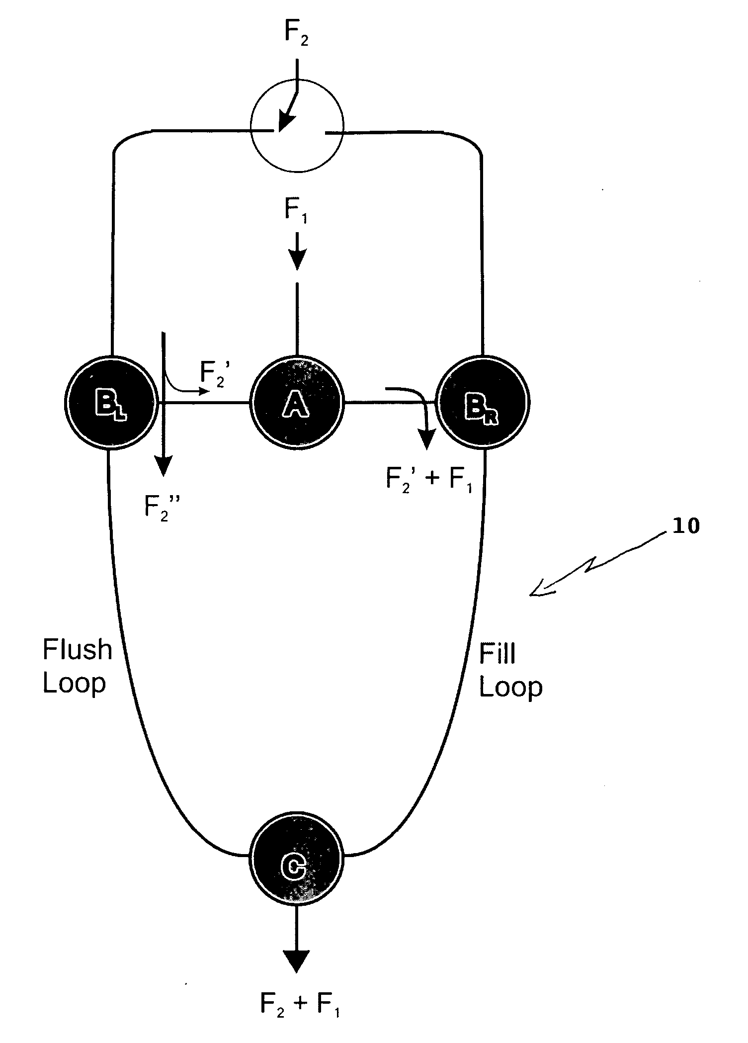
[0092] Theoretically, pulses of primary column effluate exit the device with temporal widths given by the ratio of the loop fill rate (F.sub.1+F.sub.2') to the loop flush rate (F.sub.2") multiplied by the modulation period. Thus, the expected temporal width of an exiting pulse, w, is given by 1w = F 1 + F 2 'F 2 " = F 1 + F 2 ' F 2 - F 2 ' ( 1 )

[0093] where .tau. is the modulation period.

[0094] Inspection of Equation 1 sho...

example 3

[0102] A set of experiments was performed where the flow switching modulator sampled a series of pentane peaks. The experimental apparatus is shown in FIG. 14. A gaseous mixture of pentane in hydrogen was generated by injecting liquid pentane with a syringe pump at a rate of 0.2 .mu.L min.sup.-1 into a 5 mL min.sup.-1 flow of hydrogen. This mixture was passed through a 28 .mu.L sample loop of a multi-port diaphragm valve (VICI, Houston, Tex., USA, part number DV22-2116). The sample loop contents were injected into a 1.0 mL min.sup.-1 primary flow of H.sub.2 every 15.2 s. The pentane peaks were passed through a 500 cm.times.250 .mu.m DB-1701 column (Agilent Technologies, Palo Alto, Calif., USA) before being sampled with the flow-switching device.

[0103] Peak Shapes Under Optimal Modulation Conditions

[0104] The flow-switching device was used to modulate methane with F.sub.1=1.0 mL min.sup.-1 and F.sub.2=20.0 mL min A portion of the FID signal obtained for a modulation period of 2.0 s i...


PUM


Abstract

A fluidic switching device is particularly for use in chromatography is described. The device allows a rapid switching between chromatographic columns; particularly, in gas chromatography.

Description

[0001] This application claims priority to provisional application Ser. No. 60 / 471,640, filed May 19, 2003.[0003] The present invention relates to a fluidic switching device particularly for use in chromatography. The device is particularly useful in gas chromatography for switching between first and second columns. In particular, the device can be used in place of the high speed diaphragm valve in two dimensional gas chromatography as described in my U.S. patent application Ser. No. 10 / 067,378, filed Feb. 4, 2002, now U.S. Pat. No. 6,632,268, which is incorporated by reference in its entirety herein.DESCRIPTION OF RELATED ART[0004] John B. Phillips and Zaiyou Liu introduced comprehensive two-dimensional gas chromatography (GC.times.GC) twelve years ago (Liu, Z. Y., et al., J. Chromatogr. Sci. 29 227 (1991)). Their original design employed a two-stage thermal modulator. This modulator was effective at demonstrating the resolving power of GC.times.GC separations but not sufficiently ...

Claims


Application Information

Patent Timeline
IPC IPC(8): G01N30/02G01N30/20G01N30/38G01N30/46
CPCG01N30/20G01N30/463G01N30/465G01N30/466G01N2030/025G01N2030/383
Inventor SEELEY, JOHN V.
Owner OAKLAND UNIVESITY
Learn More