Electrophoretic display with a bi-modal particle system
a particle system and electrophoretic display technology, applied in the field of electrophoretic display with a bimodal particle system, can solve the problems of inferior image bistability, image uniformity and colloidal stability, and significant deterioration of dmin or % reflectance in the current dispersion system availabl
- Summary
- Abstract
- Description
- Claims
- Application Information
AI Technical Summary
Benefits of technology
Problems solved by technology
Method used
Image
Examples
preparation 1
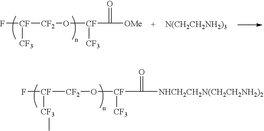
Synthesis of Perfluorinated Reactive Dispersant R.sub.f amine 4900
[0053] 2
[0054] 48 Gm of Krytox.RTM. methyl ester (DuPont, MW=about 4800, n=about 30) was dissolved in 100 gm of 1,1,2-trichlorotrifluoroethane (Aldrich). The resultant solution was added drop by drop into a solution containing 7.3 gm of tris(2-aminoethyl)amine (Aldrich) in 45 gm trifluorotoluene and 90 gm 1,1,2-trichlorotrifluoroethene over 2 hours with stirring at room temperature. The mixture was then stirred for another 8 hours to allow the reaction to complete. The IR spectrum of the crude product clearly indicated the disappearance of C.dbd.O vibration for methyl ester at 1780 cm.sup.-1. and the appearance of C.dbd.O vibration for the amide product at 1695 cm.sup.-1. Solvents were removed by rotary evaporation. The crude product was then dissolved in 250 ml of PFS2 solvent (perfluoropolyether from Solvay Solexis) and extracted with 100 ml of ethyl acetate three times, then dried over magnesium sulfate to yield 42...
preparation 2
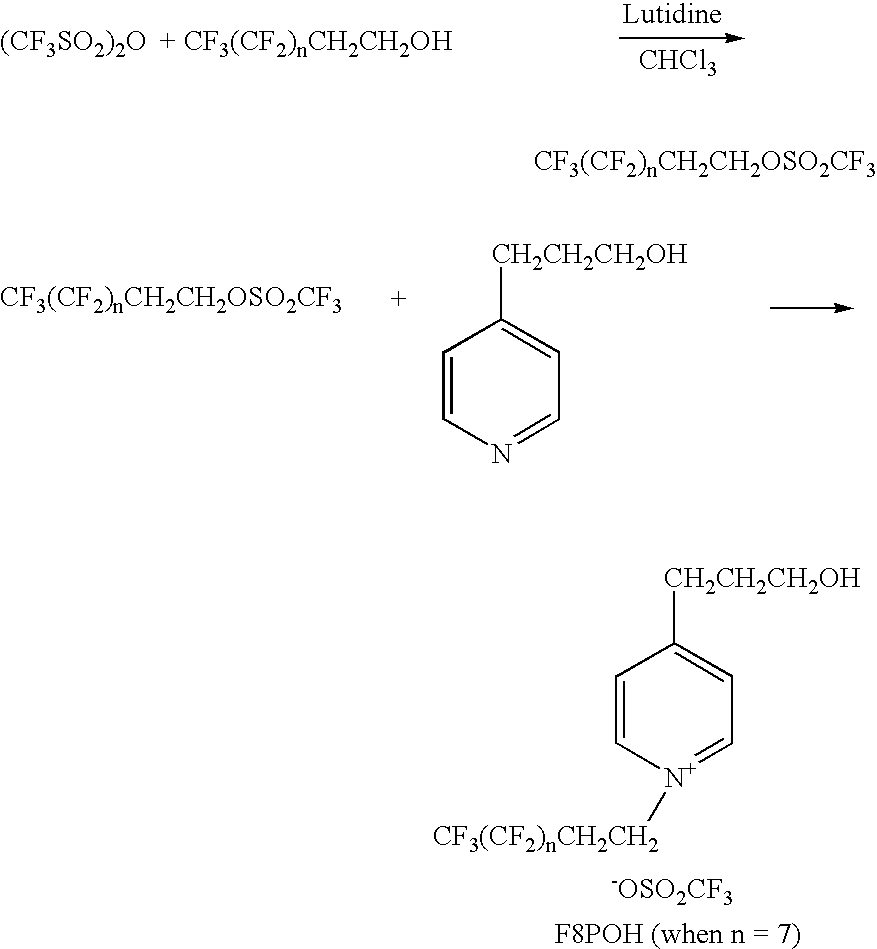
Synthesis of a Reactive Fluorinated Pyridinium Salt
[0056] 3
[0057] 3.21 Gm (30.0 mmol) of 2,6-lutidine (Aldrich) and 11.6 gm (25.0 mmol) of 1H, 1H, 2H, 2H-perfluorodecanol [CF.sub.3(CF.sub.2).sub.nCH.sub.-2CH.sub.2OH, n=7] were dissolved in 150 ml of chloroform in a flask and cooled in a 0.degree. C. bath. To the solution, 8.5 gm (30.0 mmol) of trifluoromethanesulfonic anhydride pre-dissolved in 100 ml of chloroform was added drop-wise with stirring over a period of 30 minutes. The mixture was stirred for at least another 8 hours at room temperature to allow the reaction to complete. The reaction mixture was washed with deionized water three times, dried over magnesium sulfate and the solvent was stripped off. The crude product was recrystallized from heptane / methylene chloride and rinsed with heptane. 12.45 Gm (yield: 83.6%) of a white crystal (1H,1H, 2H, 2H-perfluorodecyl triflate, CF.sub.3(CF.sub.2).sub.nCH.sub.2CH.sub.2OSO.sub.2CF.sub.3, n=7) was obtained.
[0058] 5.96 Gm (10 mmol)...
preparation 3
Preparation of TiO.sub.2-Containing Microparticles
[0063] 9.05 Gm of Desmodur.RTM. N3400 aliphatic polyisocyanate (from Bayer AG) and 0.49 g of triethanolamine (99%, Dow) were dissolved in 3.79 gm of MEK (methyl ethyl ketone). To the resultant solution, 13 gm of TiO.sub.2 R706 (DuPont) was added and homogenized for 2 minutes with a rotor-stator homogenizer (IKA ULTRA-TURRAX T25, IKA WORKS) at ambient temperature. A solution containing 1.67 gm of 1,5-pentanediol (BASF), 1.35 gm of polypropylene oxide (mw=725 from Aldrich), 2.47 gm of MEK and 0.32 gm of a 2% dibutyltin dilaurate (Aldrich) solution in MEK was added and further homogenized for 2 minutes. In the final step, 0.9 gm of R.sub.f-amine 4900 from Preparation 1 in 40.0 gm of HT-200 (Solvay Solexis) was added and homogenized for 2 minutes, followed by addition of additional 0.9 gm of R.sub.f-amine 4900 in 33.0 g of HT-200 and homogenization for 2 minutes. A TiO.sub.2-containing microparticle dispersion with low viscosity was obta...
PUM
| Property | Measurement | Unit |
|---|---|---|
| diameter | aaaaa | aaaaa |
| diameter | aaaaa | aaaaa |
| diameter | aaaaa | aaaaa |
Abstract
Description
Claims
Application Information
 - R&D
- Intellectual Property
- Life Sciences
- Materials
- Tech Scout
- Unparalleled Data Quality
- Higher Quality Content
- 60% Fewer Hallucinations
Browse by: Latest US Patents, China's latest patents, Technical Efficacy Thesaurus, Application Domain, Technology Topic, Popular Technical Reports.
© 2025 PatSnap. All rights reserved.Legal|Privacy policy|Modern Slavery Act Transparency Statement|Sitemap|About US| Contact US: help@patsnap.com


