
Autodiscriminating bar code reading apparatus having solid state image sensor

a bar code and image sensor technology, applied in the field of hand-held optical reading devices, can solve the problems of affecting the reading process, etc., and unable to be dealt with in this way for a long tim

Inactive Publication Date: 2004-10-21
LONGACRE ANDREW JR +4
View PDF8 Cites 81 Cited by
  • Summary
  • Abstract
  • Description
  • Claims
  • Application Information

AI Technical Summary

Benefits of technology

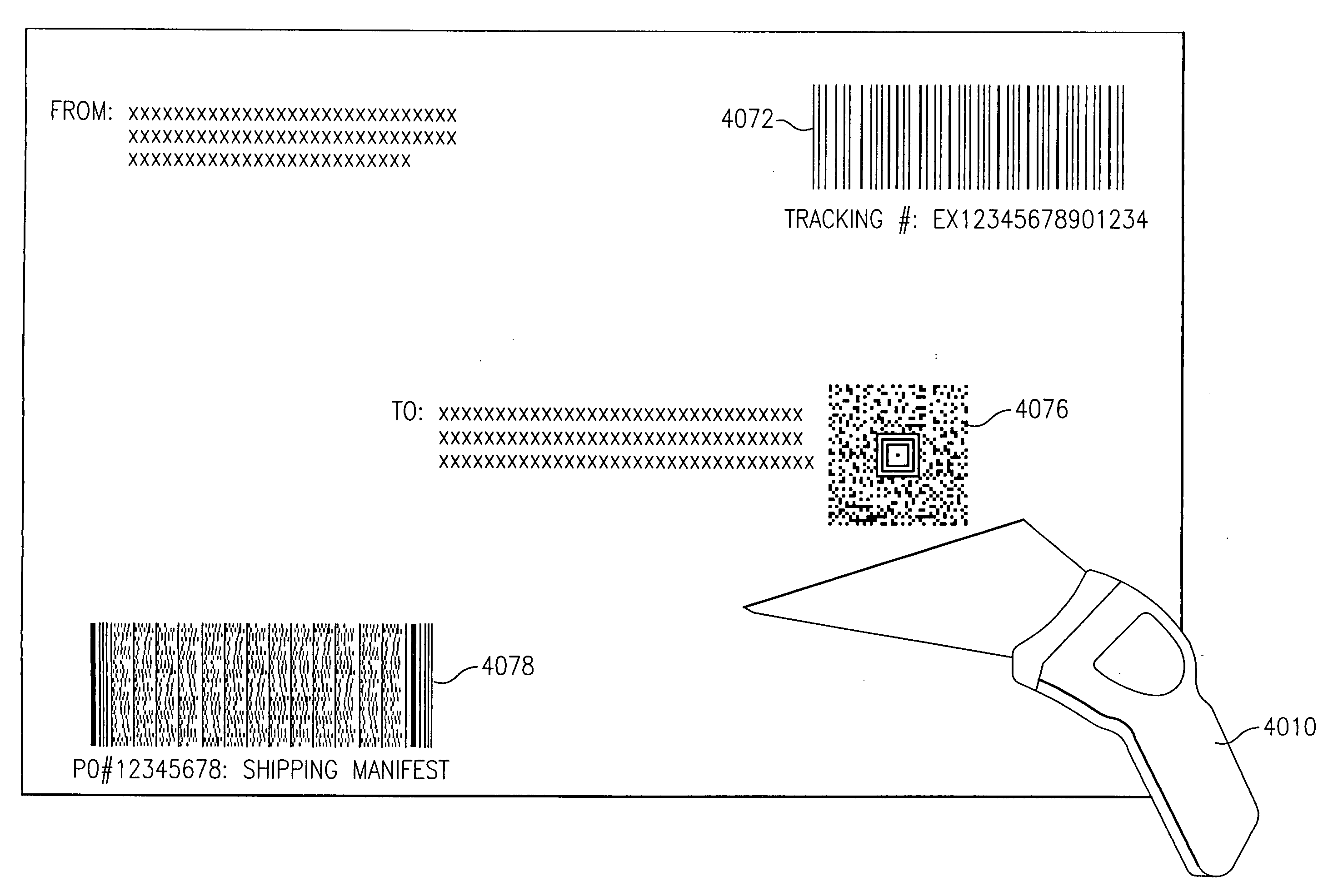
[0335] As will be explained more fully presently, one important advantage of the present invention is its ability to determine, solely from information contained in a succession of imaged slices or scans, when to stop acquiring data from the 2D symbol. The present invention accomplishes this by examining the bit representations of successive imaged slices, substantially in real time, for indications of the presence of the types of finders that are used with 2D bar code symbologies. Among these finders are "peripheral" type finders, such as those used with the DataMatrix symbology, "waistband" type finders such as those used with the Code One symbology, and "central" or "bullseye" type finders, such as those used by the Maxicode and Aztec symbologies. The last mentioned symbology is described in copending U.S. patent application Ser. No. 08 / 441,446, filed May 15, 1995, entitled "Two Dimensional Data Encoding Structure and Symbology For Use With Optical Readers".

Problems solved by technology

Readers of the above-described type have the disadvantage that, if they are operated under relatively heavy decoding loads, i.e., are required to rapidly scan symbols that have a relatively high data content, the tracking relationship or synchronism between the scanning and decoding phases of the reading process will break down.
This is because under heavy decoding loads the decoding phase of a read operation takes longer than the scanning phase thereof, causing the decoding operation to lag behind the scanning operation.
While this time lag can be dealt with for brief periods by storing the results of successive scans in a scan memory and decoding the results of those scans in the order of their occurrence when the decoder becomes available, it cannot be dealt with in this way for long.
This is because, however large the scan memory, it will eventually overflow and result in a loss of scan data.
This is in spite of the fact that the 1D / 2D autodiscrimination is known to involve heavy decoding loads of the type that give rise to tracking problems.
As new and / or improved 1D and 2D bar code symbologies, and as additional 1D and 2D decoding programs come into widespread use, previously built optical readers may or may not be able to operate therewith.
To the extent that they cannot operate therewith, such previously built optical readers will become increasingly obsolete and unusable.
Because of the expense of the former and the time delays of the latter, neither of these approaches may be practical or economical.
The above-described problem is compounded by the fact that, if an optical reader is not equipped to operate as a tracking reader, it may not be possible to reprogram it to use an autodiscrimination program that is designed to be executed in conjunction with tracking.
Alternatively, the scan rate may be decreased, although this reduction will adversely affect performance when low data content symbols are read.

Method used


Image

  • Autodiscriminating bar code reading apparatus having solid state image sensor
  • Autodiscriminating bar code reading apparatus having solid state image sensor
  • Autodiscriminating bar code reading apparatus having solid state image sensor

Examples


first embodiment

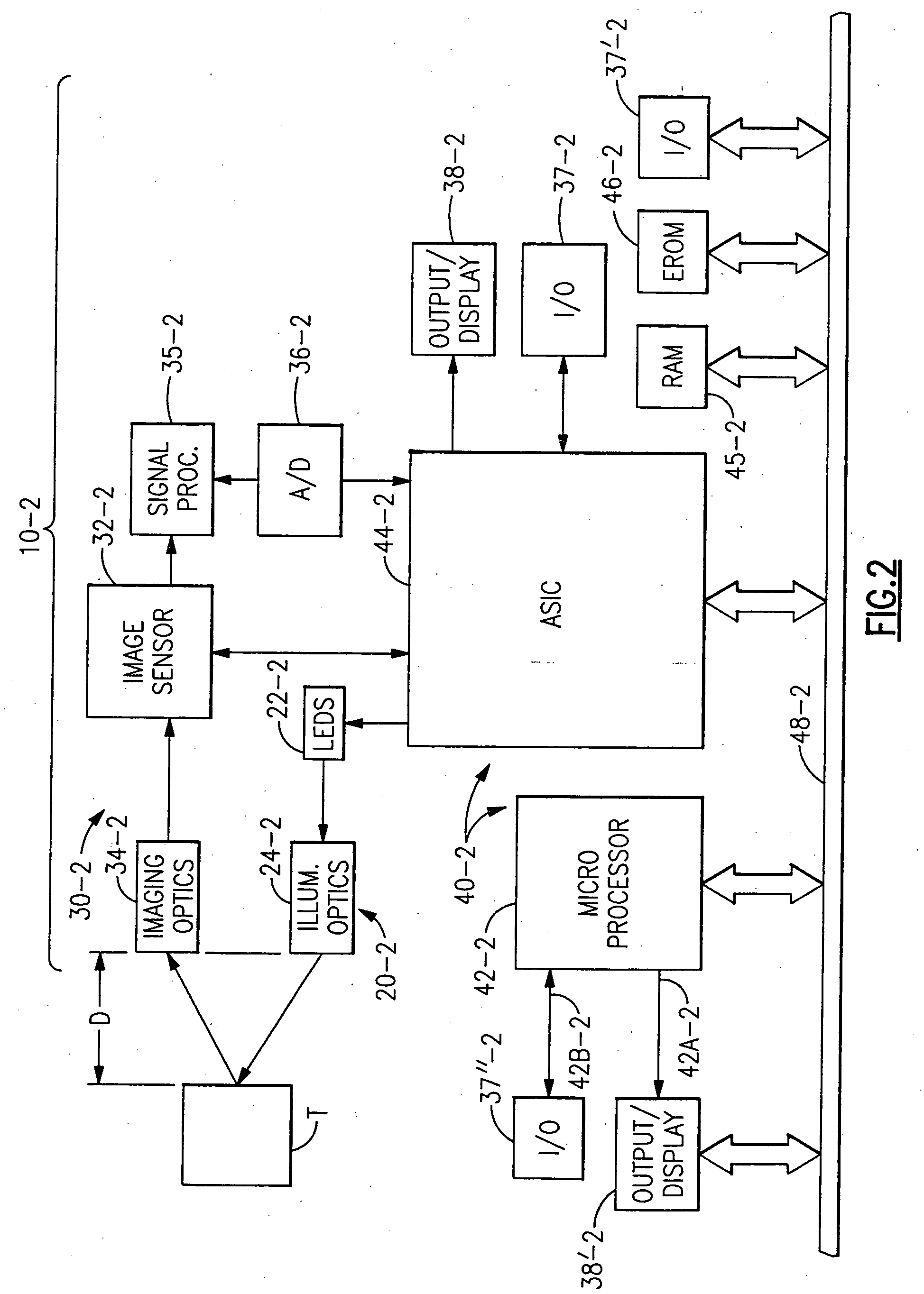
[0411] Turning now to the Drawing, and initially to FIG. 43, a bar code reader 5010 is shown. Suitable hardware comprising the reader is commercially available as model ST3000-22 from Welch Allyn, Skaneateles Falls, N.Y., and the invention can be practiced therewith provided that certain modifications disclosed herein are made. The bar code reader 5010 is a portable self-contained hand-held unit that is capable of scanning and decoding bar code symbologies. The unit could be as large as 10.times.4.times..3 inches and weigh as much as 10 oz, but It preferably has dimensions of about 71 / 2.times.31 / 2.times.2 inches, and draws 1.4 watts average during scanning, and 0.83 watts during decoding with the illumination off. It preferably weighs 7.5 oz. The unit can resolve bar code elements that are 5 mils in width.

[0412] The bar code reader 5010 has conventional optics 15 and a plurality of 660 nm light emitting diodes 5016 that illuminate a narrow strip of a bar code symbol 5018, which corr...

example 1

[0436] Using the embodiment described above, standard PDF symbols (shown representatively at reference numerals 5400, 5500, 5600 in FIGS. 46-48) were read repeatedly for 30 seconds. As previously explained, a "read" is a full operation, including scanning of the bar code information, decoding, and output of the decoded information. In this example the read head of the hand-held bar code reader was maintained in contact with the data carrier and in alignment with the row axes of the bar code symbol. There was no tilt with respect to the plane of the data carrier. Ambient room lighting conditions were present. The decoded information is shown as character sequences 5410, 5510, 5610. The results are shown in table 1.

8TABLE 1 Number of reads in 30 Seconds - According to Invention Text Error Correction Level Chars 0 1 2 3 4 5 6 7 8 100 54 61 69 75 76 75 50 27 15 200 31 43 48 59 57 53 39 24 14 400 22 28 24 25 28 25 23 18 13 800 11 14 13 16 15 16 13 12 8 1200 8 9 9 10 10 9 7 -- -- 1600 5 6...

second embodiment

[0439] Turning now to FIG. 49, there is shown a schematic of a portion of a second embodiment of the invention, wherein similar parts have the same reference numbers as in FIGS. 43 and 44. This embodiment has the same general construction as the first embodiment, except now the photodetector is realized as a two dimensional CCD matrix 5117 comprised of elements such as 5120--5120, instead of a linear CCD array. During a scanning operation the CCD array simultaneously acquires an image of the entire two dimensional bar code symbol 5018. The signals developed by the CCD matrix 5117 are multiplexed in row-wise fashion through MUX 5125, and then coupled to the signal processing circuitry 5020. With the use of the multiplexer, the two dimensional array 5117 in a single scanning operation thus emulates multiple scans executed by the linear array 5017 of the first embodiment, and the signal format is entirely acceptable to the signal processing circuitry 5020, and the microprocessor 5030, ...


PUM


Abstract

A bar code reading device processing two-dimensional electronic representations in the decoding of bar code symbols, which can automatically discriminate between code symbologies such as PDF 417 code symbology and UPC code symbology. The bar code reading device may further have improved reprogramming features and improved menuing features.

Description

CROSS REFERENCES TO RELATED APPLICATIONS[0001] This application is a continuation-in-part of copending U.S. patent application Ser. No. 09 / 385,597 filed on Aug. 30, 1999, which is a continuation-in-part of U.S. patent application Ser. No. 08 / 839,020 filed Apr. 23, 1997, which issued as U.S. Pat. No. 5,965,863 on Oct. 12, 1999, which is a continuation-in-part of U.S. patent application Ser. No. 08 / 697,913 filed Sep. 3, 1996, which issued as U.S. Pat. No. 5,900,613 on May 4, 1999, which is a continuation-in-part of U.S. patent application Ser. No. 08 / 516,185 filed Aug. 18, 1995, which is a continuation-in-part of U.S. patent application Ser. No. 08 / 205,539, filed on March 4, 1994 which issued as U.S. Pat. No. 5,463,214 on Oct. 31, 1995, the aforementioned U.S. patent application Ser. No. 08 / 697,913 also being a continuation-in-part of U.S. patent application Ser. No. 08 / 504,643 filed Jul. 20, 1995, which issued as U.S. Pat. No. 5,773,806, the aforementioned U.S. patent application Ser...

Claims


Application Information

Patent Timeline
IPC IPC(8): G06K7/10G06K7/14G06K17/00G06K19/06
CPCG06K7/10851G06K7/14G06K7/1417G06K7/1473G06K7/1491G06K17/0022G06K19/06037
Inventor LONGACRE, ANDREW JR.EHRHART, MICHAEL A.KOZIOL, THOMAS J.HUSSEY, ROBERT M.PARKER, JAMES A.
Owner LONGACRE ANDREW JR
Learn More