Suspension for running toy and running toy

a technology for running toys and toy suspensions, which is applied in the direction of toys, remote-control toys, entertainment, etc., can solve the problems of uneven characteristics of right and left coiled springs, insufficient grounding of right and left steering wheels, and vehicle toy steering cannot be steady

Inactive Publication Date: 2004-10-07
TOMY CO LTD
View PDF32 Cites 0 Cited by
  • Summary
  • Abstract
  • Description
  • Claims
  • Application Information

AI Technical Summary

Benefits of technology

[0019] Moreover, because there is no need for providing each of the right and left turning members with a biasing member, the number of components used in the suspension is decreased, and the assembly of the suspension becomes easier.
[0025] According to the suspension for a running toy, which has such a structure, because the right and left wheels are grounded to the road surface by using a biasing force which is caused by elastically deforming the biasing member provided in the middle of the width direction, the wheels can be properly grounded to the road surface.
[0026] Moreover, the number of components used in the suspension is decreased, and the assembly of the suspension becomes easier.
[0032] Moreover, the number of components used in the suspension is decreased, and the assembly of the suspension becomes easier.
[0034] According to such a running toy, because the running toy comprises any one of the suspensions for a running toy, the wheels can be properly grounded to the road surface.

Problems solved by technology

However, there are many cases that a difference in the characteristics between the right and left coiled springs is caused.
Therefore, there is some possibility that the right and left steering wheels are not properly grounded.
In this case, there is a problem that the vehicle toy cannot steer steadily.
Moreover, because each of the right and left knuckle arms is provided with a coiled spring, the assembly of the suspension is complicated.
Furthermore, there is another problem, such as, that the number of components used in the suspension becomes more.

Method used


Image

  • Suspension for running toy and running toy
  • Suspension for running toy and running toy
  • Suspension for running toy and running toy

Examples


Embodiment Construction

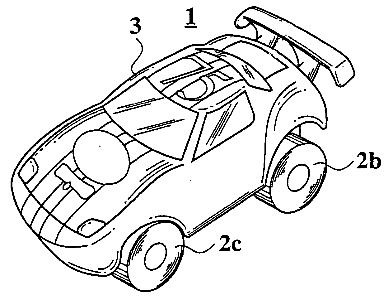
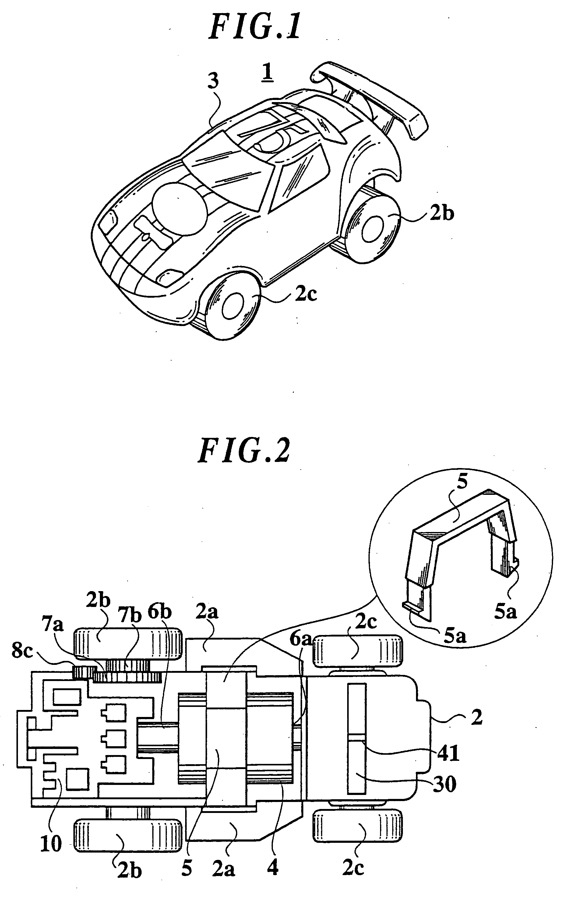
[0054] FIG. 1 is a perspective view of a racing vehicle (racing car) toy to which a suspension for a running toy according to an embodiment is applied. A housing of the vehicle toy 1 includes a chassis (base body) 2 which is shown in FIG. 2 and a body 3. The chassis 2 and the body 3 are formed out of plastic. A front portion and side portions, of the body 3 have some elasticity. The chassis 2 and the body 3 are not limited to the following structures and the like. A recess portion or a hole portion (engaging portion) is provided on an inner side of the front portion and each inner side of the side portions, of the body 3. The body 3 is fixed to the chassis 2 by elastically engaging a projection portion 2a of the chassis 2 with the recess portion or the hole portion. The vehicle toy 1 comprises an antenna (not shown in the figure) for receiving a control signal outputted from a controller which is not shown in the figure.

[0055] FIG. 2 is a plan view showing the chassis 2. A chargeabl...


PUM


Abstract

A suspension for a toy and a vehicle toy, which can properly ground right and left wheels, and includes right and left turning members for turning right and left wheels in clockwise and counterclockwise directions around respective shafts; a member for connecting the right and left turning members with each other, and for constituting a turning pair with each of the right and left turning members; and a biasing member having right and left edge portions, which is supported in a middle of a width direction of the running toy, and which extends on the right and left turning members, the right and left edge portions being elastically deformable vertically; wherein the right and left turning members are turned around the respective shafts by moving the connecting member in right and left directions; the right and left turning members are constructed so as to be movable vertically in a predetermined range; and the turning members are pressed with the right and left edge portions by using a biasing force which is caused by elastically deforming the biasing member, so that the right and left wheels are grounded to a road surface.

Description

[0001] This application claims the benefit under 35 U.S.C. .sctn.120 of pending U.S. application Ser. No. 10 / 056,112, filed Jan. 28, 2002 and entitled "Suspension for Running Toy and Running Toy," which is hereby incorporated by reference in its entirety into this application.[0002] 1. Field of the Invention[0003] The present invention relates to a suspension for a running toy and a running toy. For more detail, the present invention relates to a suspension for a running toy and a running toy, which have each simple structure, and can properly ground wheels.[0004] 2. Description of Related Art[0005] In recent years, a running toy (such as a vehicle toy) comprising right and left knuckle arms (turning member) for turning right and left steering wheels (wheel) to the right and the left around a predetermined shaft, and a tie rod (connecting member) for connecting the right and left knuckle arms with each other, which constitute a turning pair with the right and left knuckle arms, has ...

Claims


Application Information

Patent Timeline
Patent Type & Authority Applications(United States)
IPC IPC(8): A63H17/26A63H17/267A63H17/36A63H30/04
CPCA63H17/262A63H17/36A63H30/04
Inventor YONEDA, YOUSUKE
Owner TOMY CO LTD
Why Eureka
Try Eureka