Expansion valve
a technology of expansion valve and expansion valve body, which is applied in the direction of valve operating means/release devices, refrigeration components, light and heating apparatus, etc., can solve the problems of valve plug action destabilization, expansion valve may not enjoy accurate flow control, and may be noisy, etc., to achieve convenient operation and attachment, simple construction, and easy handling
- Summary
- Abstract
- Description
- Claims
- Application Information
AI Technical Summary
Benefits of technology
Problems solved by technology
Method used
Image

Examples
embodiment 1
[0055] Embodiment 1
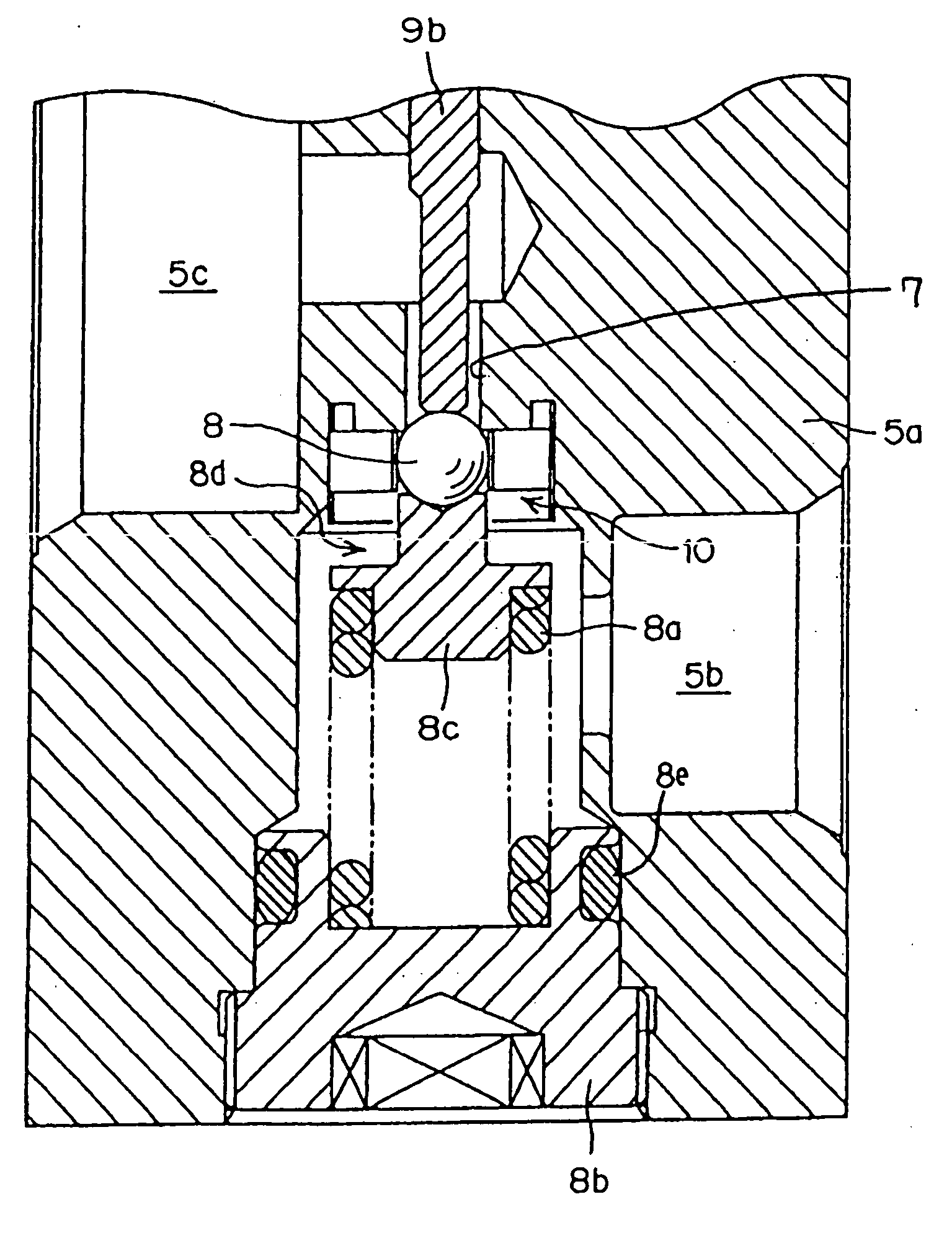
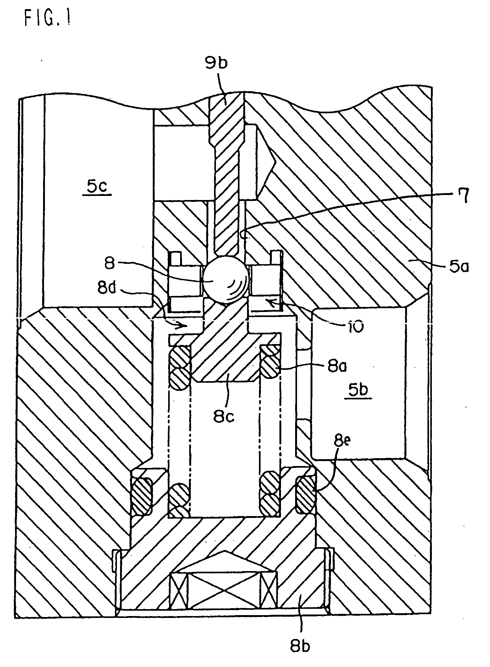
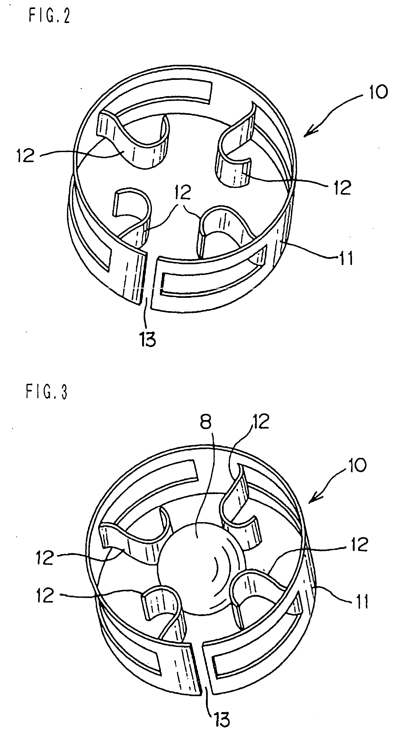
[0056] Embodiment 1 of the present invention will be described first. FIG. 1 is a sectional view showing a principal part of an expansion valve according to Embodiment 1. FIG. 2 is a perspective view of a support ring of the expansion valve. FIG. 3 is a perspective view showing the way the support ring supports a valve plug. FIG. 4 is a perspective view of another example of the support ring. In FIG. 1, like numerals are used to designate like portions of the conventional expansion valve shown in FIG. 21.
[0057] The expansion valve of Embodiment 1 is characterized in that constraint means 10 is added to the valve plug 8 of the conventional expansion valve 5 shown in FIG. 21, so that this element will be mainly described in the following. In the expansion valve 5 of Embodiment 1, its valve plug 8 is driven by a temperature sensing drive unit 9 to adjust the flow rate of a refrigerant that flows into an evaporator 6. The drive of the low-pressure refrigerant that is ...
embodiment 2
[0063] Embodiment 2
[0064] FIG. 4 shows a support ring 10a according to Embodiment 2. The support ring 10a comprises a circular annular portion 1a and vibration-proof plate springs 12a, which are arranged on one side of the annular portion 11a. In order to enable the support ring 10a, like the support ring 10 of Embodiment 1, to be reduced in diameter so that it can be set in the valve chest 8d of the valve body 5a, a slit 13a is formed in a part of the annular portion 11a.
[0065] The vibration-proof springs 12a of the support ring 10a of Embodiment 2 are curved plates of which the respective distal ends are convexed toward the center of the annular portion 11a and the respective side faces support the periphery of the valve plug 8. In Embodiment 2, as in Embodiment 1, the vibration-proof springs 12a are formed by being cut out of the annular portion 11a.
[0066] If the refrigerant pressure fluctuates in the refrigerating cycle in Embodiment 2 arranged in this manner, as in Embodiment 1...
embodiment 3
[0067] Embodiment 3
[0068] FIGS. 5 to 7 show a support ring 10b according to Embodiment 3. FIG. 5 is a perspective view of the support ring, FIG. 6 is a perspective view showing the support ring in a set state, and FIG. 7 is a perspective view showing the way the support ring supports a valve plug.
[0069] In Embodiment 3, an intersecting portion, instead of the slits 13 and 13a of Embodiments 1 and 2, is formed on the end portions of a plate that constitutes an annular portion 11b. As shown in FIG. 5, the intersecting portion is formed of a narrow tongue 11b'having a given length and a tongue receiving recess 11b", which guides and supports the tongue 11b'. The tongue 11b' extends from one end portion of the annular portion 11b, sharing the curvature with the annular portion 11b. The tongue receiving recess 11b" is formed in the other end of the annular portion 11b.
[0070] Near the other end portion of the annular portion 11b, the tongue receiving recess 11b" is formed between its uppe...
PUM
 Abstract
Description
Claims
Application Information
 - R&D
- Intellectual Property
- Life Sciences
- Materials
- Tech Scout
- Unparalleled Data Quality
- Higher Quality Content
- 60% Fewer Hallucinations
Browse by: Latest US Patents, China's latest patents, Technical Efficacy Thesaurus, Application Domain, Technology Topic, Popular Technical Reports.
© 2025 PatSnap. All rights reserved.Legal|Privacy policy|Modern Slavery Act Transparency Statement|Sitemap|About US| Contact US: help@patsnap.com