
Stump cutter device and cutter insert unit for the stump cutter device

a stump cutter and cutter insert technology, which is applied in the direction of manufacturing tools, flat surfacing machines, tableware, etc., can solve the problems of increased wear, damage to the holder, and difficulty in adjusting the holder,

Inactive Publication Date: 2004-09-09
BETEK BERGBAU UND HARTMETALLTECHN KARL HEINZ SIMON
View PDF10 Cites 11 Cited by
  • Summary
  • Abstract
  • Description
  • Claims
  • Application Information

AI Technical Summary

Benefits of technology

[0013] It is a another object of this invention to provide a cutter insert unit of the type mentioned above but in which a lateral wear of the cutter insert unit in the area of the cutter head is prevented and thus increases the service life of the entire cutting tool is clearly increased.
[0014] This object is achieved with the shank of the cutter insert unit respectively having at least a tapering shank section and at least a widened shank section. The holder has a recess with protrusions corresponding to the tapering shank section and an undercut area corresponding to the widened shank section and thus provides a positive connection between the shank and the holder which is particularly resistant and rugged. With this type of interlock between the shank of the cutter insert unit and the holder, forces acting on them are evenly distributed and therefore protect the material from premature wear. This connection provides an easy mounting of the cutter insert unit in the holder.
[0015] The lateral guidance of the shank of the cutter insert unit in the holder, and the exact position of the shank during mounting in the holder is achieved because the recess of the holder is cut in the shape of an open depression into the holder. The depression has a wall opposite the open side, and the cutter insert unit rests against the wall with a lateral surface of its shank. The shank is laterally guided in the mounted state between the wall and the rotating body of the stump cutting device. The wall also prevents dirt from entering the area of the recess.

Problems solved by technology

However, damage can occur from nails around which the tree stump has grown, or from stones.
The cutting tools must be easily exchangeable because of this damage and of the wear occurring during the operation.
One disadvantage of this device is the complicated structure of the holder because of the peg, and in an elaborate assembly of the parts.
Furthermore, the forces occurring during the operation act on comparably small surfaces of the shank and the holder, which results in increased wear.
It is disadvantageous with this device for the cutting tools, which are angled with respect to the contact face, to have a complicated shape and are therefore elaborate to produce.
The forces acting on the cutter insert units lead to a torsional strain on the shank in the recess.

Method used


Image

  • Stump cutter device and cutter insert unit for the stump cutter device
  • Stump cutter device and cutter insert unit for the stump cutter device
  • Stump cutter device and cutter insert unit for the stump cutter device

Examples


Embodiment Construction

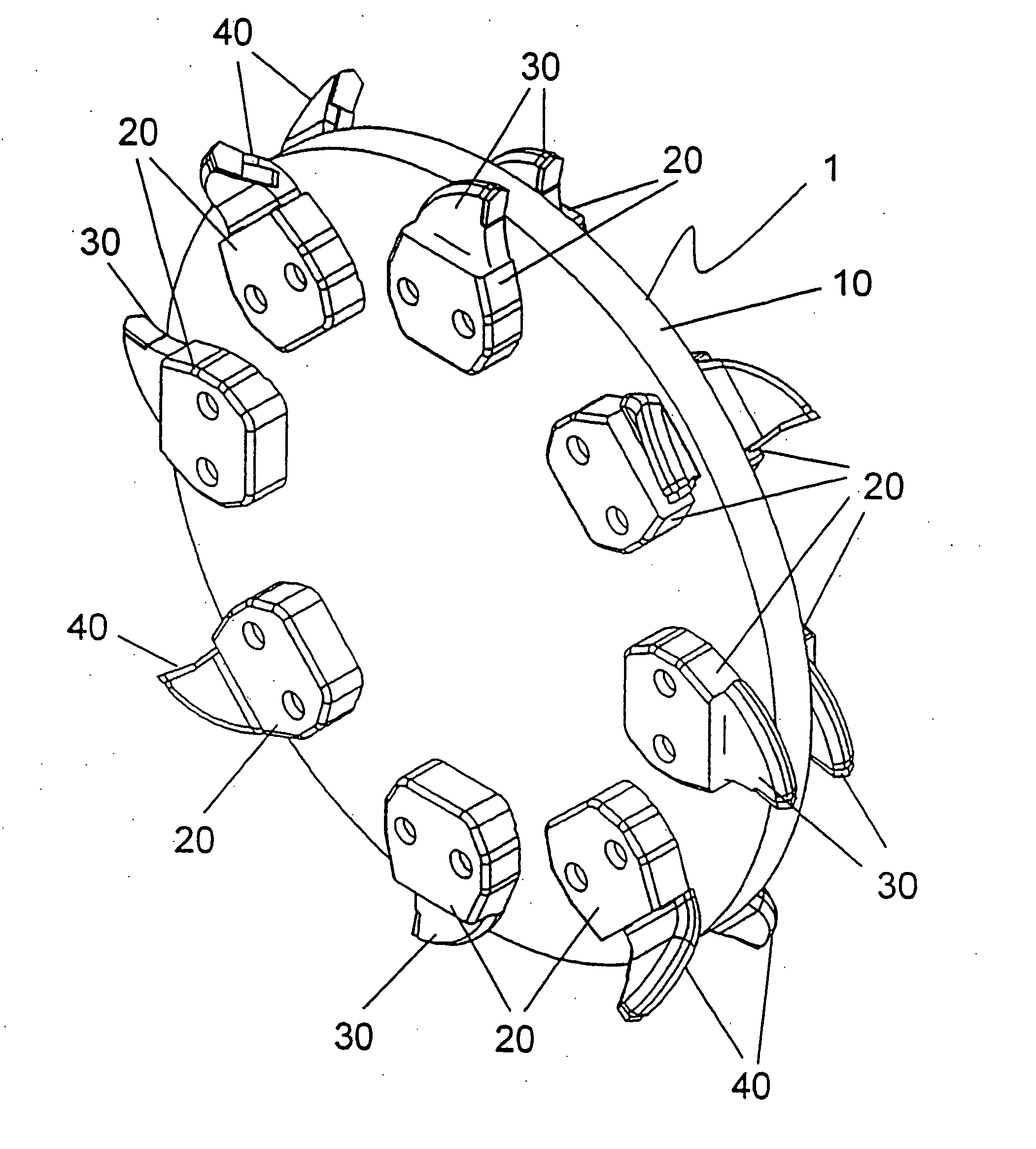
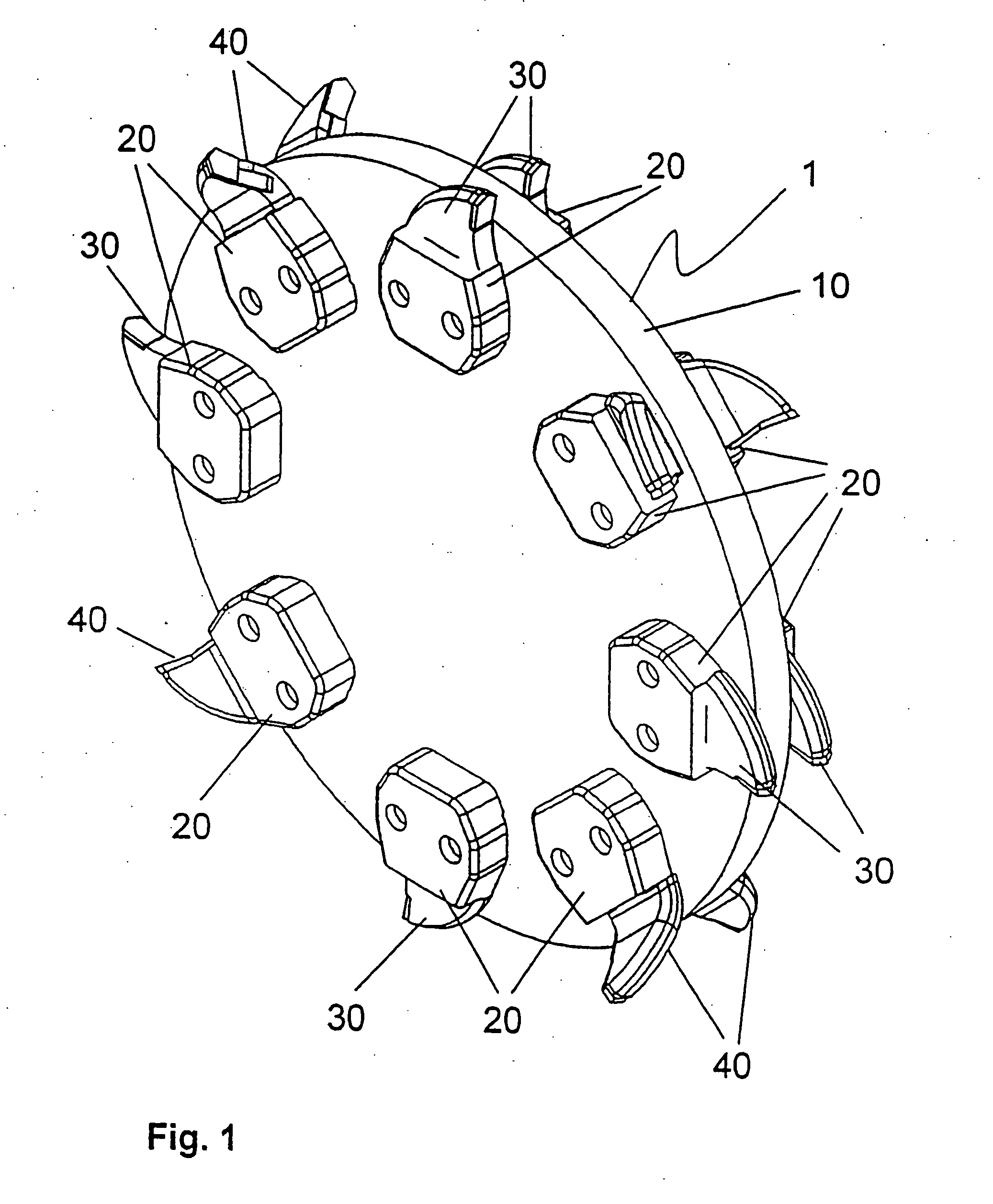
[0041] A stump cutting device is shown in FIG. 1. Several cutter insert units 30, 40 are fastened in pairs on both sides of the circumference of a rotating body 10, here in the form of a rotating disk, by holders 20. In the represented case, cutter insert units 30 in a straight embodiment alternate with cutter insert units 40 in an angled embodiment. Depending on the type of use, the number of cutter insert units 30, 40 used can be matched to the respective job, wherein the number of straight cutter insert units 30 and / or angled cutter insert units 40 can be varied.

[0042] The holder 20 for the cutter insert units 30,40 is shown in various views in FIG. 2a to FIG. 2d.

[0043] The holder 20 comprises a shaped body of metal having an exterior 25, and an interior 24 which points toward the rotating body 10 in the mounted state. The holder 20 also has bores 21, which are suitable for fastening the holder 20 to the rotating body 10 by screw connections.

[0044] In the upper area of the interi...


PUM

PropertyMeasurementUnit
Thicknessaaaaaaaaaa
Areaaaaaaaaaaa

Abstract

A cutting tool for a stump cutter device, having a holder and at least one cutter insert unit, wherein the cutter insert unit has a cutter head and a shank, and wherein the cutter insert unit can be connected with the holder by its shank. To achieve a simple and cost-effective tool exchange, along with the simultaneous low wear of the contact faces, the shank of the cutter insert unit respectively has at least a tapering shank section and at least a widened shank section. The holder has a recess with protrusions corresponding to the tapering shank section and an undercut area corresponding to the widened shank section and thus provides a positive connection between the shank and the holder.

Description

[0001] 1. Field of the Invention[0002] This invention relates to a cutting tool for a stump cutter device, having a holder and at least one cutter insert unit, wherein the cutter insert unit has a cutter head and a shank, and the cutter insert unit can be connected with the holder by its shank. This invention also relates to a cutter insert unit, having a cutter head, a shank and a cutter insert, wherein the shank is arranged at an angle with respect to the cutter head, and the cutter head has a front cutting edge which is formed at least partially by a cutter insert of a mechanically resistant material.[0003] 2. Discussion of Related Art[0004] A known cutting tool and such a cutter insert are taught by German Patent Reference DE 690 21 215 and U.S. Pat. No. 5,497,815.[0005] Such cutting tools are used in tree stump cutting devices that have a vertical disk, which can be rotated by a motor and on which cutting tools are mounted. To remove a tree stump, the rotary disk is rotated and...

Claims


Application Information

Patent Timeline
IPC IPC(8): A01G23/06
CPCY10T407/26A01G23/067
Inventor KAMMERER, KARL
Owner BETEK BERGBAU UND HARTMETALLTECHN KARL HEINZ SIMON
Learn More