
Electrically powered brake system

a technology of brake system and electric motor, which is applied in the direction of brake system, brake components, instruments, etc., can solve the problems of affecting the simplification and compactization of automotive vehicles, and affecting the entire number of vehicle wheels

Active Publication Date: 2004-08-26
NTN CORP
View PDF13 Cites 8 Cited by
  • Summary
  • Abstract
  • Description
  • Claims
  • Application Information

AI Technical Summary

Benefits of technology

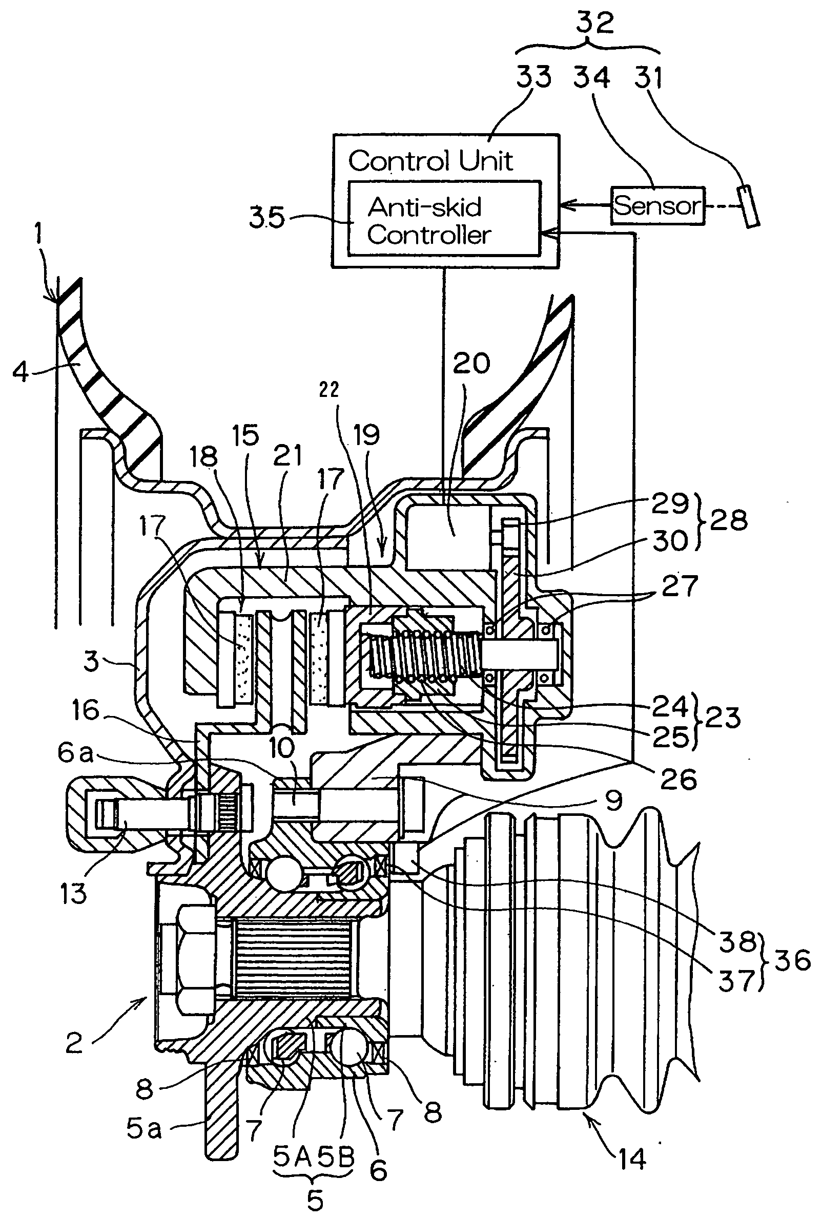
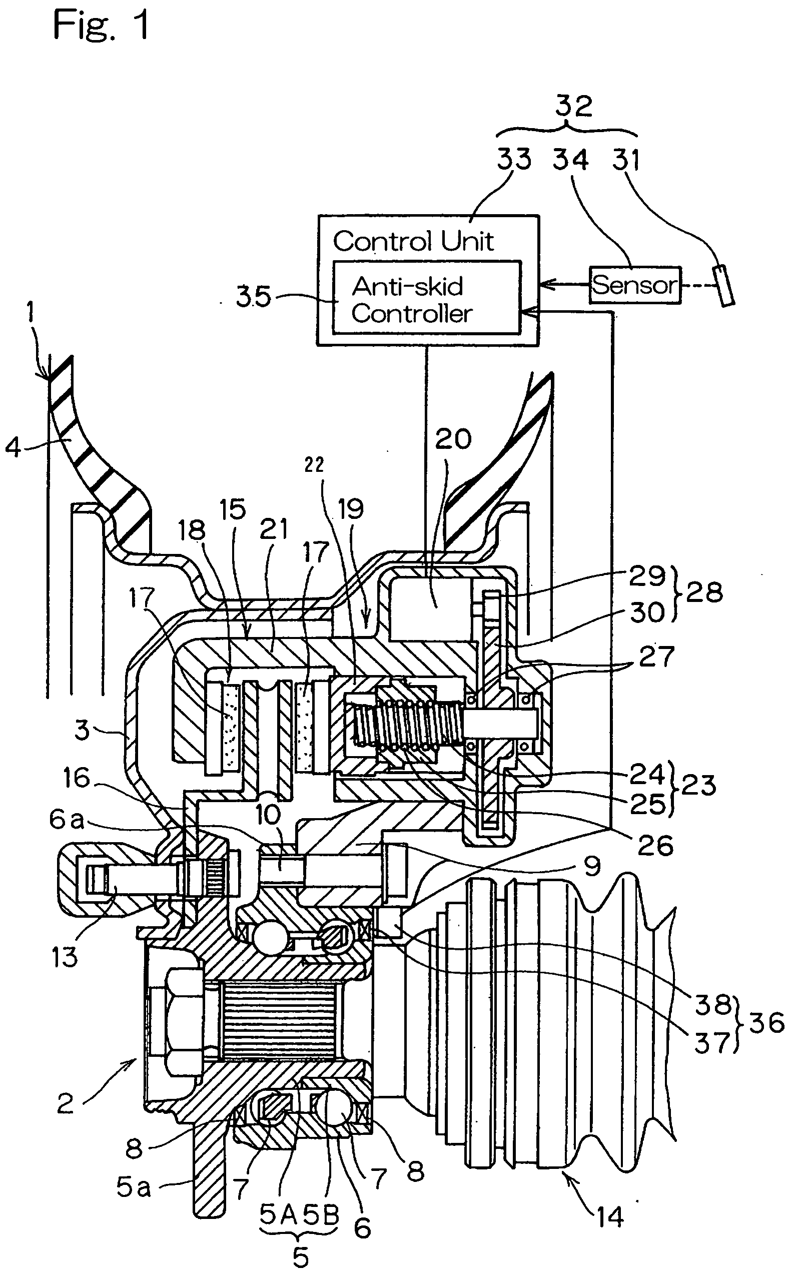
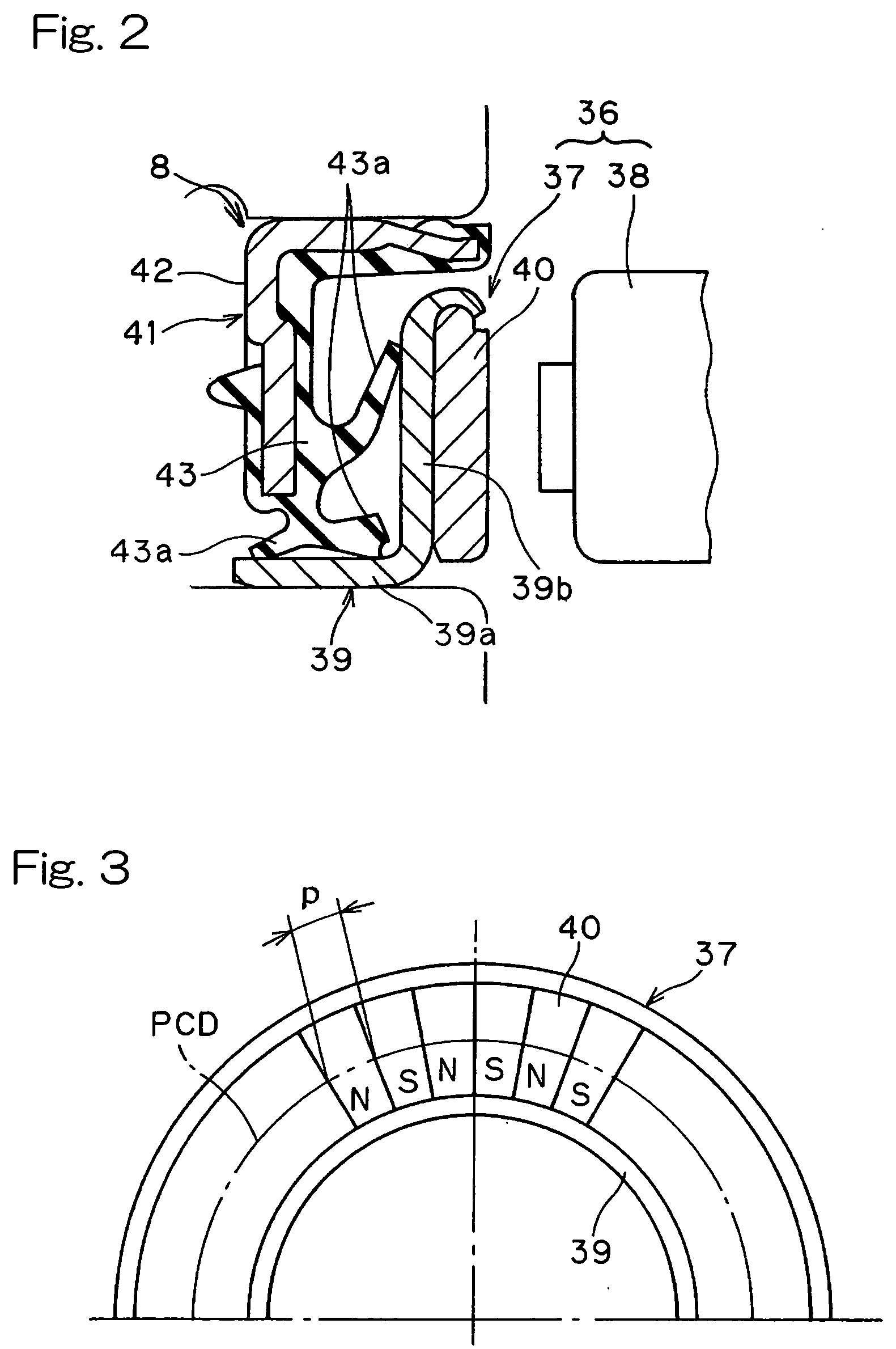
[0012] In order to accomplish these objects of the present invention, the electrically powered brake system herein disclosed includes a brake wheel mounted on a vehicle wheel for rotation together therewith; an actuating unit including brake pieces frictionally engageable with the brake wheel; a drive unit for translating a rotary output of an electric drive motor into a rectilinear reciprocating motion by means of a ball screw mechanism, which rectilinear reciprocating motion is transmitted to the brake pieces as a braking force; an operating unit for controlling the electric drive motor according to manipulation of an operating member; a rotation detector including a magnetic encoder and a sensor, the magnetic encoder being mounted on a rotating side member of a wheel support bearing assembly for supporting the vehicle wheel and having a plurality of opposite magnetic poles alternating in a direction circumferentially thereof, the sensor being mounted in face-to-face relation with the magnetic encoder for detecting passage of the opposite magnetic poles; an anti-skid controller for regulating the braking force, exerted by the electric drive motor, in dependence on the number of revolutions of the vehicle wheel detected by the rotation detector during a braking effected by manipulation of the operating member, to thereby prevent rotation of the vehicle wheel from being locked.
[0013] According to the present invention, when the operating member is operated to effect a braking, the electric drive motor can be driven under the control of the operating unit and rotation of the electric drive motor is then translated through the ball screw mechanism into a rectilinear reciprocating motion that is assumed by the brake pieces with the brake wheel consequently clamped by the brake pieces, thereby achieving the braking. At this time, the anti-skid controller regulates the braking force, exerted by the electric drive motor, in dependence on the number of revolutions of the vehicle wheel 1 to thereby prevent the rotation of the vehicle wheel 1 from being locked. Thus, the provision of the anti-skid controller in the electrically powered brake system is effective in that the braking force can be regulated with a high response to the detection of rotation of the vehicle wheel, allowing an accurate braking to be carried out. Also, the use of the electric drive motor as a source of drive is effective to substantially eliminate the need to use any hydraulic equipments and hydraulic pipe lines and, therefore, the structure around the vehicle wheel can advantageously be simplified.
[0014] Also, since as a mechanism for converting the rotary motion of the electric motor into the rectilinear reciprocating motion the ball screw mechanism, also known as the ball-and-nut mechanism, is employed, the output from the electric drive motor can be highly efficiently transmitted and the rectilinear motion can be a short distance motion relative to the rotary motion, resulting in that the relatively high braking force for a small output of the electric motor can be obtained. Yet, since the rotation detector for detecting the rotational speed of the vehicle wheel makes use of the magnetic encoder capable of producing a magnetic field as an element to be detected, it is in the form of an active detector having an excellent sensitivity. For these reasons, in combination with the braking characteristics of the electrically powered brake system having a high response, an accurate braking can be achieved with a further appropriated regulation of the braking force.
[0016] Where the anti-skid controller is utilized to individually and separately control the vehicle wheels, it is possible to make best use of the excellent response characteristics of the drive unit in which the electric drive motor and the ball screw mechanism are utilized, so that the vehicle wheels tending to exhibit different numbers of revolutions during, for example, the automotive vehicle cornering or running along the tortuous road can be further effectively braked under the properly exercised anti-skid control.
[0018] In this wheel support bearing assembly according to the present invention, since the rotation detector for detecting the rotational speed of the vehicle wheel makes use of the magnetic encoder capable of producing a magnetic field as an element to be detected, it is in the form of an active detector having an excellent sensitivity. For this reason, in combination with the braking characteristics of the electrically powered brake system having a high response, an accurate braking can be achieved with a further appropriated regulation of the braking force. Where the magnetic encoder is incorporated in the sealing unit as described above, compactization and reduction in number of component parts used and in number of assembling steps can advantageously be achieved.
[0019] In a preferred embodiment of the present invention, the magnetic encoder employed in the wheel support bearing assembly may include a ring-shaped core metal made of a metallic material and forming a part of the sealing unit, and a ring-shaped multi-pole magnet disposed on a surface of the core metal. The multi-pole magnet is preferably a member having a plurality of opposite magnetic poles N and S magnetized to alternate in a direction circumferentially thereof, in which case the neighboring opposite magnetic poles N and S are preferably spaced at intervals of a predetermined pitch p that is chosen to be not greater than 1.5 mm, with a single pitch deviation of .+-.3%. The single pitch deviation referred to above is represented by the difference in distance between the magnetic poles detected at the position spaced a predetermined distance from the multi-pole magnet, which is expressed by the ratio relative to a target pitch. With this feature residing in the wheel support bearing assembly, it is possible to achieve the detection of rotation with high precision.

Problems solved by technology

Also, the hydraulically operated brake device requires the use of hydraulic equipments such as, for example, a hydraulic pump, a drive motor for driving the hydraulic equipments and associated hydraulic supply and drain pipes and, accordingly, simplification and compactization of an automotive vehicle tend to be hampered.
While to simplify the hydraulic system, double or single hydraulic systems are generally employed in one automotive vehicle, failure of the hydraulic pump and / or the drive motor to operate properly may adversely affect the entire number of vehicle wheels that are placed under the control of the same hydraulic system.

Method used


Image

  • Electrically powered brake system
  • Electrically powered brake system
  • Electrically powered brake system

Examples


Embodiment Construction

[0028] A first preferred embodiment of the present invention will be described with particular reference to FIGS. 1 to 4. The electrically powered brake system shown therein is designed to control a vehicle wheel 1 and is rotatably mounted on a wheel support bearing assembly 2. The vehicle wheel 1 includes a rim 3 on which a tire 4 is mounted. The wheel support bearing assembly 2 includes an inner race 5, an outer race 6 positioned radially outwardly of the inner race 5 with an annular bearing space defined between it and the inner race 5, and a plurality of rows of rolling elements 7 operatively accommodated within the annular bearing space between the inner race 5 and the outer race 7. The annular bearing space has its opposite open ends sealed by respective sealing units 8. The outer race 6 is connected with a vehicle body structure (not shown) through a wheel suspension device 9 while a vehicle wheel 1 is fitted to the inner race 5 in any known manner.

[0029] While the wheel supp...


PUM


Abstract

To provide an electrically powered brake system capable of performing a control of the braking force appropriate to a particular wheel rotational speed with high response and capable of being simplified in structure with no need to employ any hydraulic equipment and the related pipe lines, the electrically powered brake system includes an actuating unit 18 including a brake wheel 16 mounted on a vehicle wheel 1 and brake pieces 17 frictionally engageable with the brake wheel 16. A drive unit 19 is operable to translate a rotary output of an electric drive motor 20 into a rectilinear reciprocating motion by means of a ball screw mechanism 23, which rectilinear reciprocating motion is transmitted to the brake pieces 17 as a braking force. An operating unit 32 is operable to control the electric drive motor 20 according to manipulation of an operating member 31 such as, for example, a brake pedal. An anti-skid control device 35 is provided for regulating the braking force, exerted by the electric drive motor 20, in dependence on the number of revolutions of the vehicle wheel 1 during a braking effected by manipulation of the operating member 31. For a rotation detector 1 for detecting the number of revolutions of the vehicle wheel 1, the rotation detector 1 including a magnetic encoder 37 is employed.

Description

[0001] 1. Field of the Invention[0002] The present invention generally relates to an electrically powered brake system for use in an automotive vehicle.[0003] 2. Description of the Prior Art[0004] The power plant employed in automotive vehicles appears to go through changes from the internal combustion engine that consumes petroleum as a fuel to the hybrid power plant comprised of an internal combustion engine and an electric drive motor that are selectively brought into operation one at a time depending on the operating conditions, or to the power plant comprised of only an electric drive motor.[0005] For the brake device employed in automotive vehicles, an alternative to the hydraulically operated brake device has been suggested, which comprises an electrically powered brake device including an electric drive motor utilized to drive a brake piece. In allowing the brake piece to be linearly moved reciprocatingly between activated and released positions, some of the electrically pow...

Claims


Application Information

Patent Timeline
IPC IPC(8): B60T8/171B60T8/1761B60T8/32B60T8/58B60T13/74F16D65/14F16D65/18G01P3/44
CPCB60T8/3255B60T8/329B60T13/741G01P3/443F16D2121/24F16D2125/40F16D2125/48F16D65/18
Inventor OHTSUKI, HISASHITAKAKI, MASUO
Owner NTN CORP
Learn More