
Dynamically configured 3-D object creation system with built-in printhead failure correction mechanism

a technology of failure correction mechanism and dynamic configuration, which is applied in the field of dynamic configuration of 3d object creation system with built-in failure correction mechanism, to achieve the effect of increasing substrate speed and speed

Active Publication Date: 2004-07-29
3D SYST INC
View PDF14 Cites 48 Cited by
  • Summary
  • Abstract
  • Description
  • Claims
  • Application Information

AI Technical Summary

Benefits of technology

The present invention is a method for creating objects using a production line that creates each object by creating portions of it using different subsystems. Each portion has its own voxel size and can be different from other portions. The portions can be of the same design or different designs. The objects can be created simultaneously on multiple substrates. The portions can be positioned on top of each other or offset. The printheads used to create the portions can be arranged in a longitudinally extending production line, and the substrates can move past them at a constant speed. The printheads can print across the substrate width simultaneously, and there can be multiple layer groups with different printheads. The ratio of printheads to materials can be different for each layer group. The invention allows for the creation of objects with complex designs and can create multiple objects simultaneously.

Problems solved by technology

However, these systems typically utilize a single scanning printhead and are only useful for producing non-working models.

Method used


Image

  • Dynamically configured 3-D object creation system with built-in printhead failure correction mechanism
  • Dynamically configured 3-D object creation system with built-in printhead failure correction mechanism
  • Dynamically configured 3-D object creation system with built-in printhead failure correction mechanism

Examples


Embodiment Construction

[0148] Basic Concept

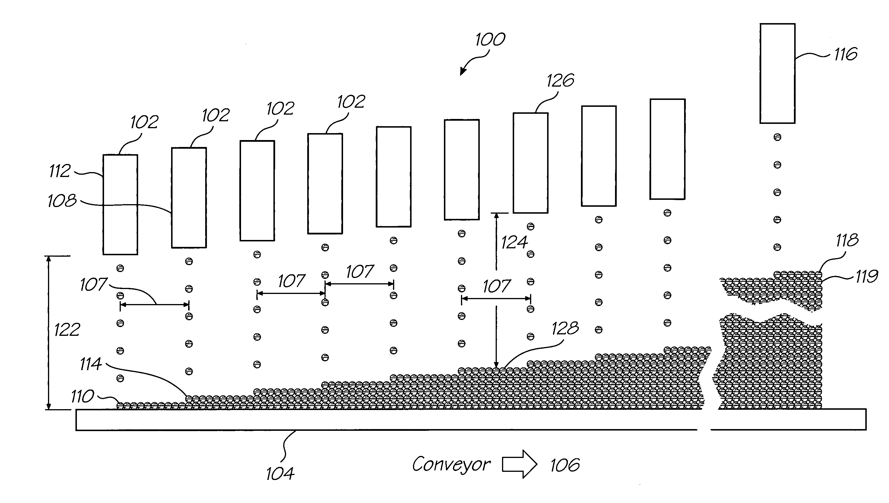
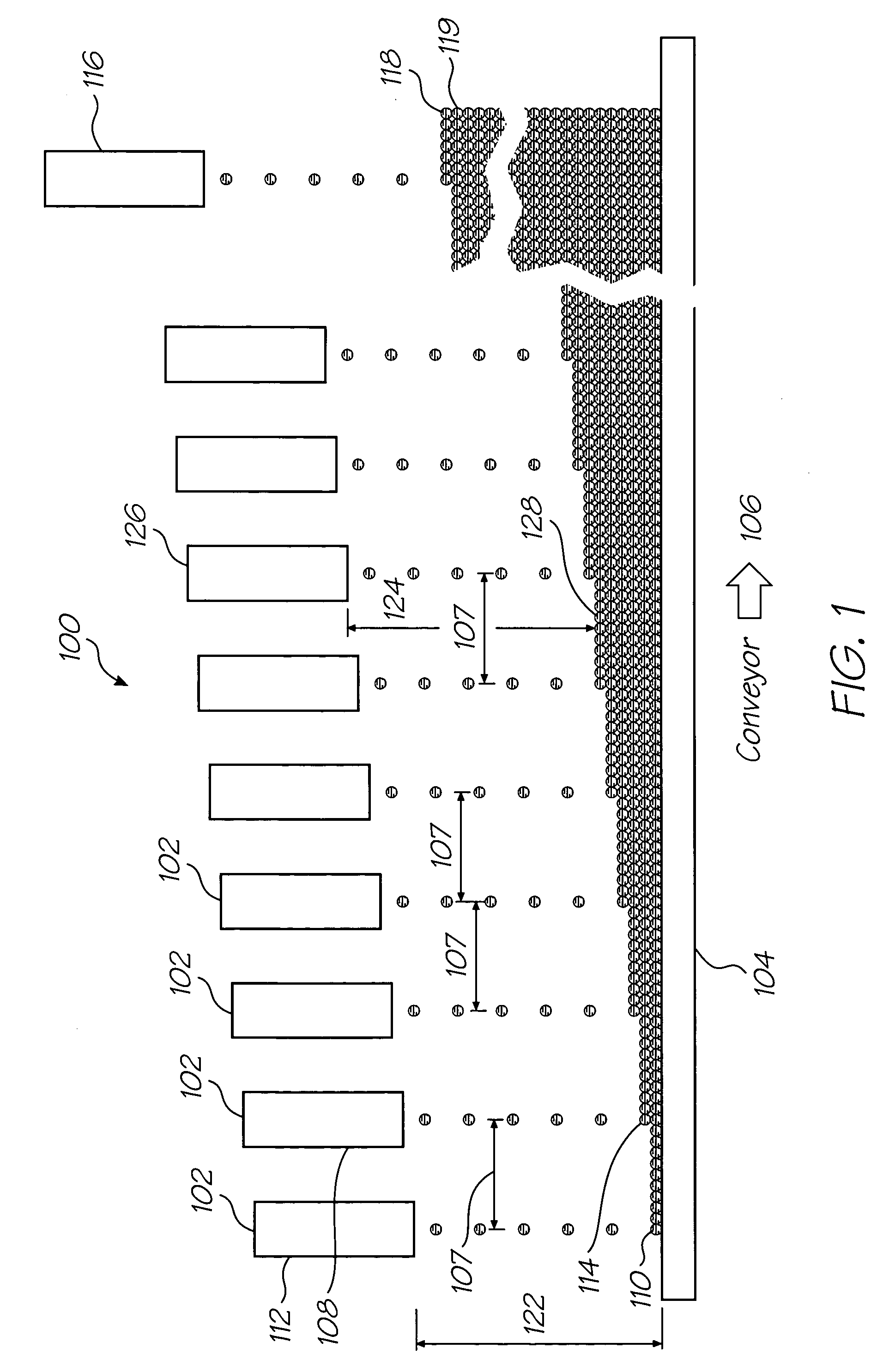
[0149] FIG. 1 schematically shows a simplified production line 100 having many substrate width printheads 102. The printheads 102 print materials onto a moving substrate 104, that is preferably moved at a substantially constant speed in a flat plane, as indicated by arrow 106. The printheads 102 extend across the width of the substrate 104 perpendicular to the direction of travel of the substrate and are, preferably, spaced along the substrate 104 with substantially constant separations. However, as will be explained later, constant separation of the printheads is not critical.

[0150] The printheads 102 print one layer of an object onto the previously printed layer. Thus the printhead 112 prints the first layer 110, the second printhead 108 prints a second layer 114 onto the first layer 110 and the N.sup.th printhead 116 prints an N.sup.th layer 118 onto the (n-1).sup.th layer 119. For clarity only one printhead is shown for each layer but in practice there will b...


PUM

PropertyMeasurementUnit
viscositiesaaaaaaaaaa
widthaaaaaaaaaa
heightaaaaaaaaaa

Abstract

A three dimensional object creation system that prints objects layer by layer, the system including a plurality of printheads, the system printing at least part of each of multiple layers simultaneously, the system configured to enable at least one first printhead that is initially configured to print at least part of a first layer to be dynamically reconfigured to print at least part of a second layer, and wherein if at least one printhead initially configured to print the second layer fails whilst printing said second layer, said at least one first printhead is dynamically reconfigured to complete the printing of at least part of said second layer.

Description

[0001] This invention relates to the creation of objects using digital additive manufacturing and more particularly to creating working objects that may be electrically and / or mechanically active.CO-PENDING APPLICATIONS[0002] Various methods, systems and apparatus relating to the present invention are disclosed in the following co-pending applications filed by the applicant or assignee of the present invention simultaneously with the present application:[0003] DAM01US, DAM02US, DAM03US, DAM04US, DAM05US, DAM07US, DAM08US, DAM09US, DAM10US, DAM11US, DAM12US, DAM13US, DAM14US[0004] The disclosures of these co-pending applications are incorporated herein by cross-reference. Each application is temporarily identified by its docket number. This will be replaced by the corresponding USSN when available.[0005] Digital additive manufacturing is a process by which an object is defined three dimensionally by a series of volume elements (hereinafter referred to as voxels). The object is then p...

Claims


Application Information

Patent Timeline
Patent Type & Authority Applications(United States)
IPC IPC(8): B29C67/00B29C70/68B41J2/01B41J3/407B41J3/54B41J11/00
CPCB22F3/008B29C67/0059B29C70/68B41J2/01Y10T29/49144B41J3/543B41J11/002Y10S439/901B05C5/0212B41J3/4073B29C64/112B33Y70/00B33Y30/00B33Y40/00B33Y80/00B33Y10/00H05K1/185H05K3/125H05K3/4664B22F10/10Y02P10/25B41J11/0021B41J11/0022B41J11/0024B41J11/00214B41J11/00216B22F12/53B22F12/70B22F12/20B33Y50/02B41J29/393
Inventor SILVERBROOK, KIA
Owner 3D SYST INC
Learn More