Ultrasound image focusing method and relative ultrasound system

a technology of ultrasonic image and relative ultrasound, applied in the field of ultrasonic image focusing method and relative ultrasound system, can solve the problems of affecting the complete image generation of the image, the curve of the delay used in receive focusing varies through, and the image is substantially distorted

Active Publication Date: 2004-07-22
ACTIS ACTIVE SENSORS
View PDF4 Cites 17 Cited by
  • Summary
  • Abstract
  • Description
  • Claims
  • Application Information

AI Technical Summary

Benefits of technology

0040] FIG. 2 is a schematic representation of the effect of the lateral sen...

Problems solved by technology

It is evident that the images obtained in this manner are substantially distorted, cannot be used directly and must be processed.
However, this procedure requires more than one pulse to obtain each single trace, and therefore drastically delays generation of the complete image.
However, this means that the curve of the delays used in receive focusing varies through time, as with the passing of time ultrasounds coming from increasingly large depths reach the array in the reception phase.
Correct implementation of dynamic receive focusing poses a few practical problems.
It is not easy to continuously modify the curve of delays used to combine the traces, discretization of the variations, d...

Method used


Image

  • Ultrasound image focusing method and relative ultrasound system
  • Ultrasound image focusing method and relative ultrasound system
  • Ultrasound image focusing method and relative ultrasound system

Examples


Embodiment Construction

[0082] 1. Description of the Processing Method

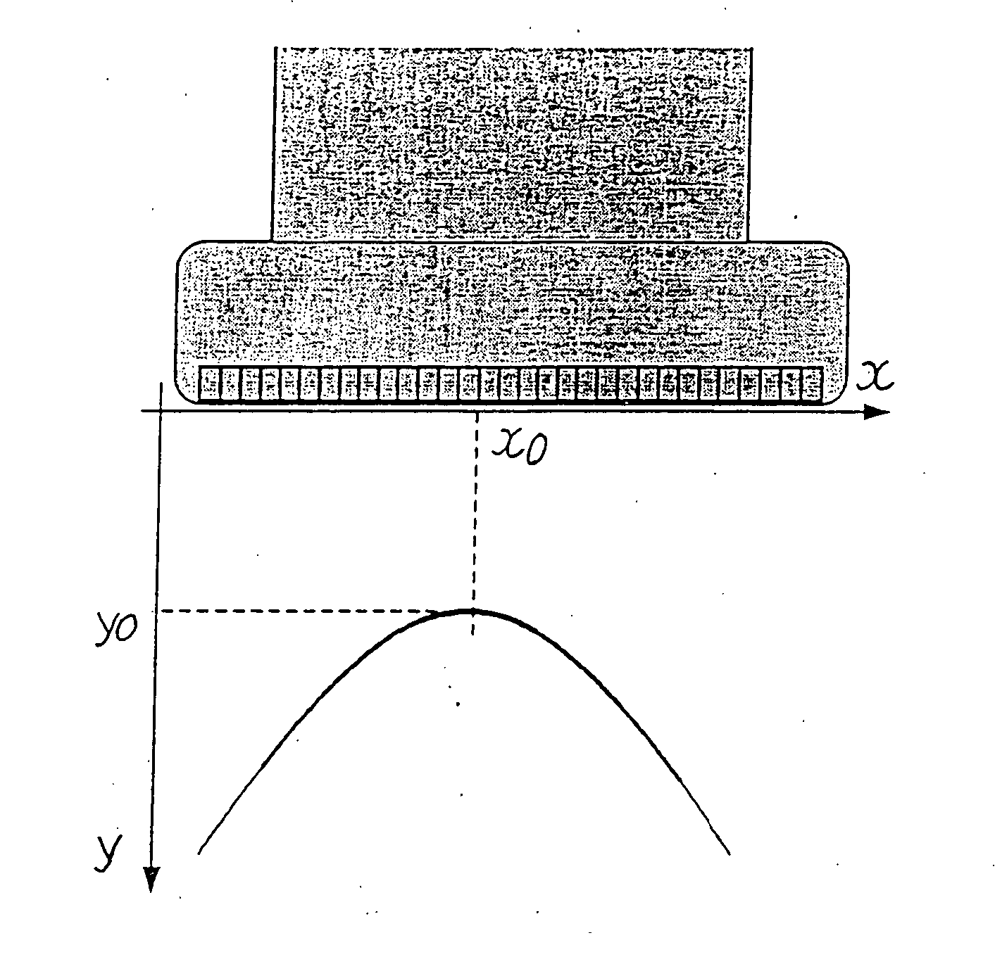
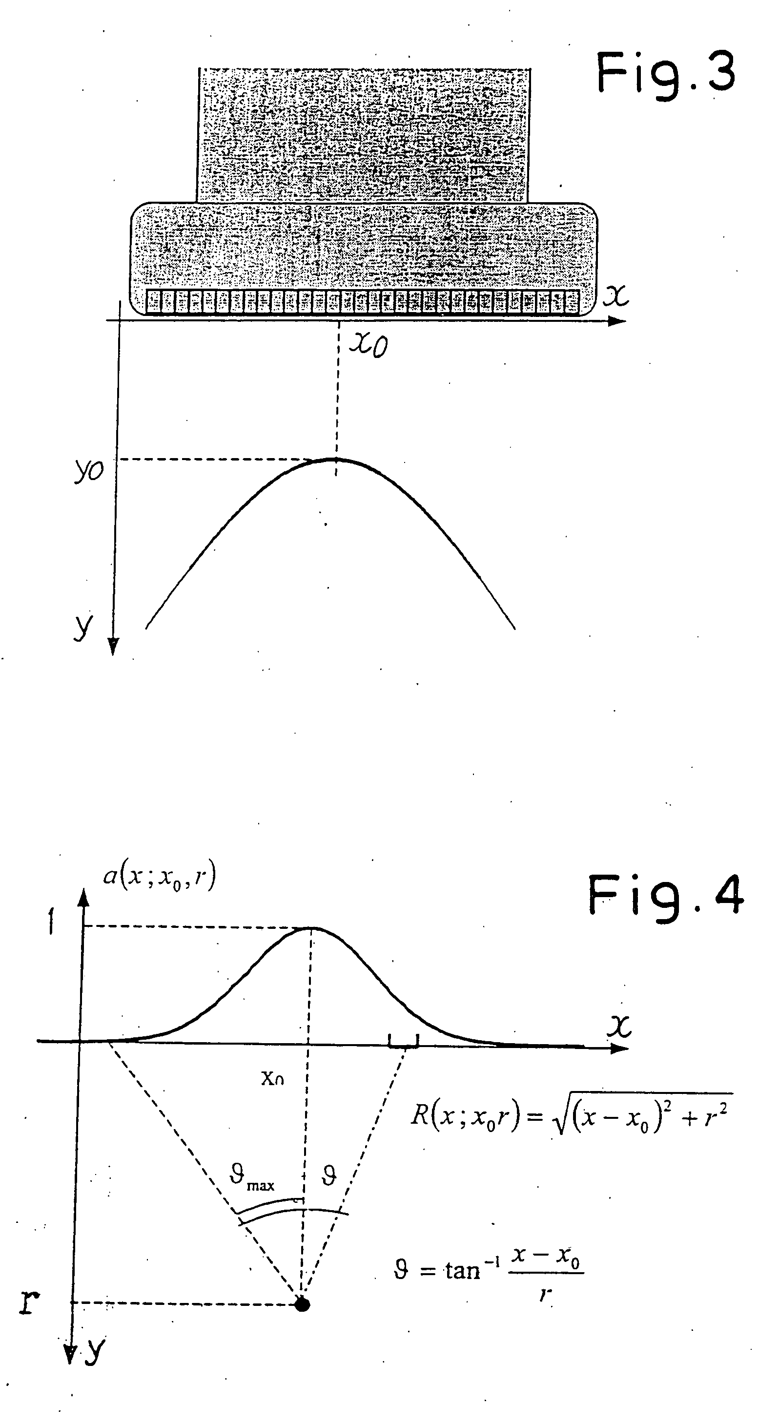
[0083] FIG. 3 schematically shows an ultrasound probe S with an array of transducers Tr aligned in the x direction, hereinafter also called main direction of the array of transducers. In the method of the present invention the transducers Tr are excited in sequence to emit an ultrasound signal. In the example illustrated here, the signal emitted is frequency modulated, meaning that it is a "chirp" signal. The signal reflected from the reflectors contained in the tissue--or in the body being investigated--for each ultrasonic signal emitted by a single transducer influences a large number of transducers in the array, which perceive it with different amplitudes according to the angle of incidence, although only the electric signal produced by the transducer that transmitted the impulse is used to generate the image.

[0084] The lateral sensitivity of each transducer forming the array has a bell-shaped pattern with a maximum at the level of it...


PUM


Abstract

The method comprises the phases of: sending a series of excitation ultrasonic signals to a volume being investigated, by means of an array of transducers aligned in a transverse direction (x), said ultrasonic signals propagating in depth in said volume according to a direction of propagation (y); acquiring, by means of said transducers, signals reflected from reflectors located in the volume being investigated; performing on said reflected signals a transform in the transverse direction from a spatial domain (x,y), defined by said transverse direction (x) and by said direction of propagation (y), to a first transformed domain; applying, in the transformed domain, a two-dimensional transformation, to straighten every curved image (Ip1, Ip2, Ip3) of a reflector in said volume being investigated and make it essentially orthogonal to the direction of propagation (y); compressing, in the transverse direction (x) each of the straightened curves (Im1, Im2, Im3) to concentrate said straightened image in a zone centered at the level of the position of said reflector along said transverse direction (x).

Description

[0001] The present invention relates to an ultrasound image focusing method, and in particular to perform focusing in a transverse direction, that is in the direction parallel to the extension of the array of transducers forming the ultrasound probe.[0002] The invention also relates to an ultrasound system, i.e. an ultrasound instrument that implements said method.PRIOR ART[0003] Probes generally used In ultrasound investigations are composed of a series of transducers or piezoelectric elements disposed in a one-dimensional array, or of a single mechanical scanning transducer. Ultrasound scans are produced by placing side by side the traces obtained from different transducers, or from different positions of the single transducer in the case of a single element probe. The transducers generate ultrasonic signals that propagate in the body to be investigated and receive the ultrasonic signal reflected from the reflectors located in the body. The image of the inside of the body examined...

Claims


Application Information

Patent Timeline
IPC IPC(8): G01S15/89G06T9/00
CPCG01S15/8918G06T9/007
Inventor BIAGI, ELENAMASOTTI, LEONARDOSCABIA, MARCOROSSI, IACOPODREONI, NICOLA
Owner ACTIS ACTIVE SENSORS
Why Eureka
Try Eureka