
Dynamic pitch correction in press cured power transmission belts

a technology of power transmission belts and dynamic pitch correction, which is applied in the direction of driving belts, belts/chains/gearrings, domestic applications, etc., can solve the problems of excessive pitch error, difficult to accurately measure the exact circumference of the belt slab, and cumulative pitch and tooth position errors, etc., to achieve small compensating error and large unacceptable tooth pitch errors

Inactive Publication Date: 2004-07-01
VEYANCE TECH
View PDF2 Cites 2 Cited by
  • Summary
  • Abstract
  • Description
  • Claims
  • Application Information

AI Technical Summary

Benefits of technology

[0030] According to another aspect of the present invention, the method further comprises the step of rotating the cylinders forward or backward so that a partially vulcanized belt tooth may readily engage its respective tooth cavity.
[0071] One advantage of this invention is that the cumulative error generated by measuring and curing each section of the belt in an "end to end" manner can be detected before the last section is molded, and a small compensating error can be spread evenly over several molded sections of the belt. By introducing small, acceptable errors to several molded sections, a large unacceptable tooth pitch error is avoided in the last molded section.

Problems solved by technology

Statistical variation of material properties, thermal expansion, and dimensional variation of uncured belt components often result in cumulative error of pitch and tooth position when a synchronous power transmission belt is cured incrementally in a press.
This cumulative error can result in excessive pitch error when a leading portion of the last section is cured to a trailing portion of the first section.
The exact circumference of the belt slab is difficult to measure accurately because the radius of the belt neutral plane on the cylinders is difficult to determine.

Method used


Image

  • Dynamic pitch correction in press cured power transmission belts
  • Dynamic pitch correction in press cured power transmission belts
  • Dynamic pitch correction in press cured power transmission belts

Examples


Embodiment Construction

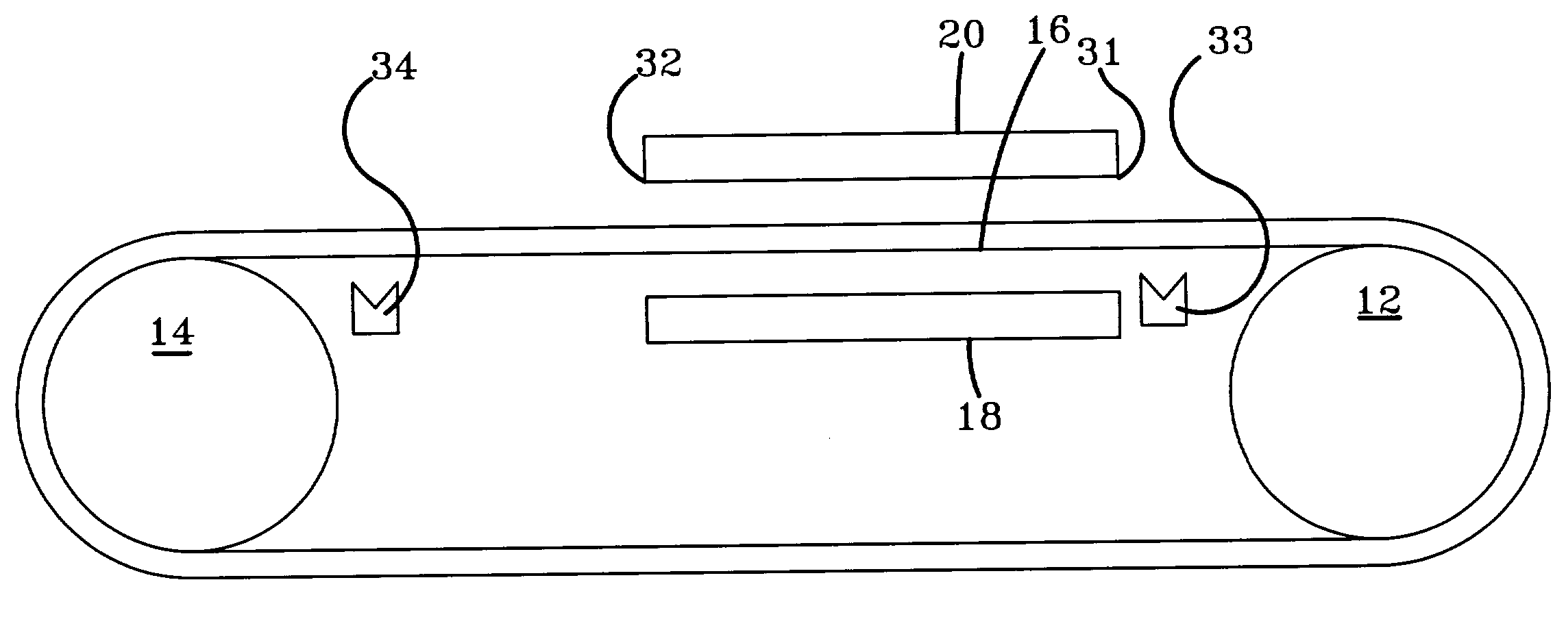
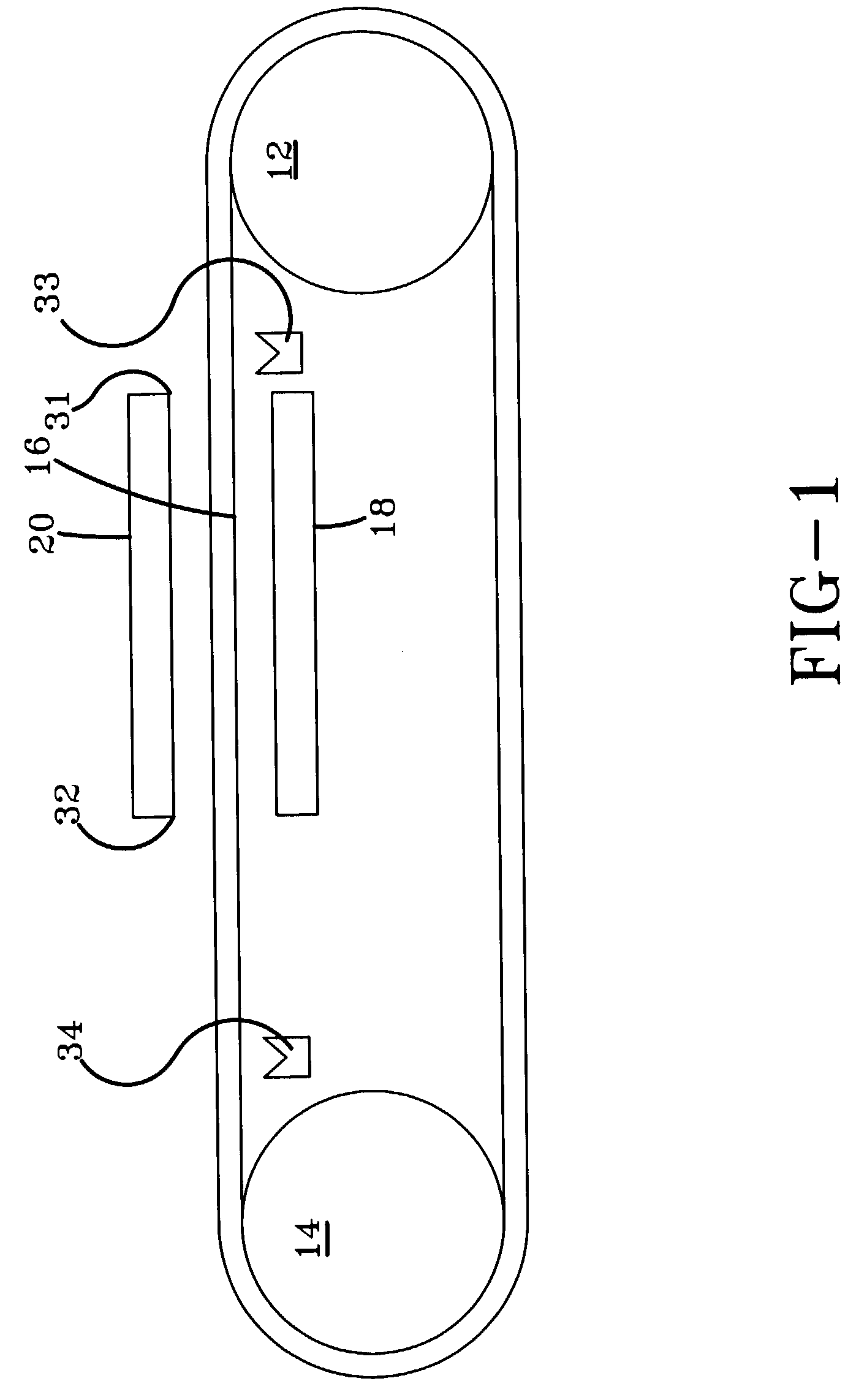
[0078] Referring now to the drawings wherein the showings are for purposes of illustrating a preferred embodiment of the invention only and not for purposes of limiting the same, FIG. 1 shows a schematic view of the innovative method and manufacturing machine according to the invention.

[0079] With continuing reference to FIG. 1, the manufacturing machine 10 includes a first cylinder 12 and a second cylinder 14. In the preferred embodiment, the first cylinder 12 is fixed and the second cylinder 14 is movable, so that the distance between the centers of the two cylinders can vary, thus, increasing or decreasing the tension on the belt 16 which is wrapped around the cylinders 12, 14. However, in other, currently unpreferred embodiments, the centers of each of the cylinders 12, 14 can move.

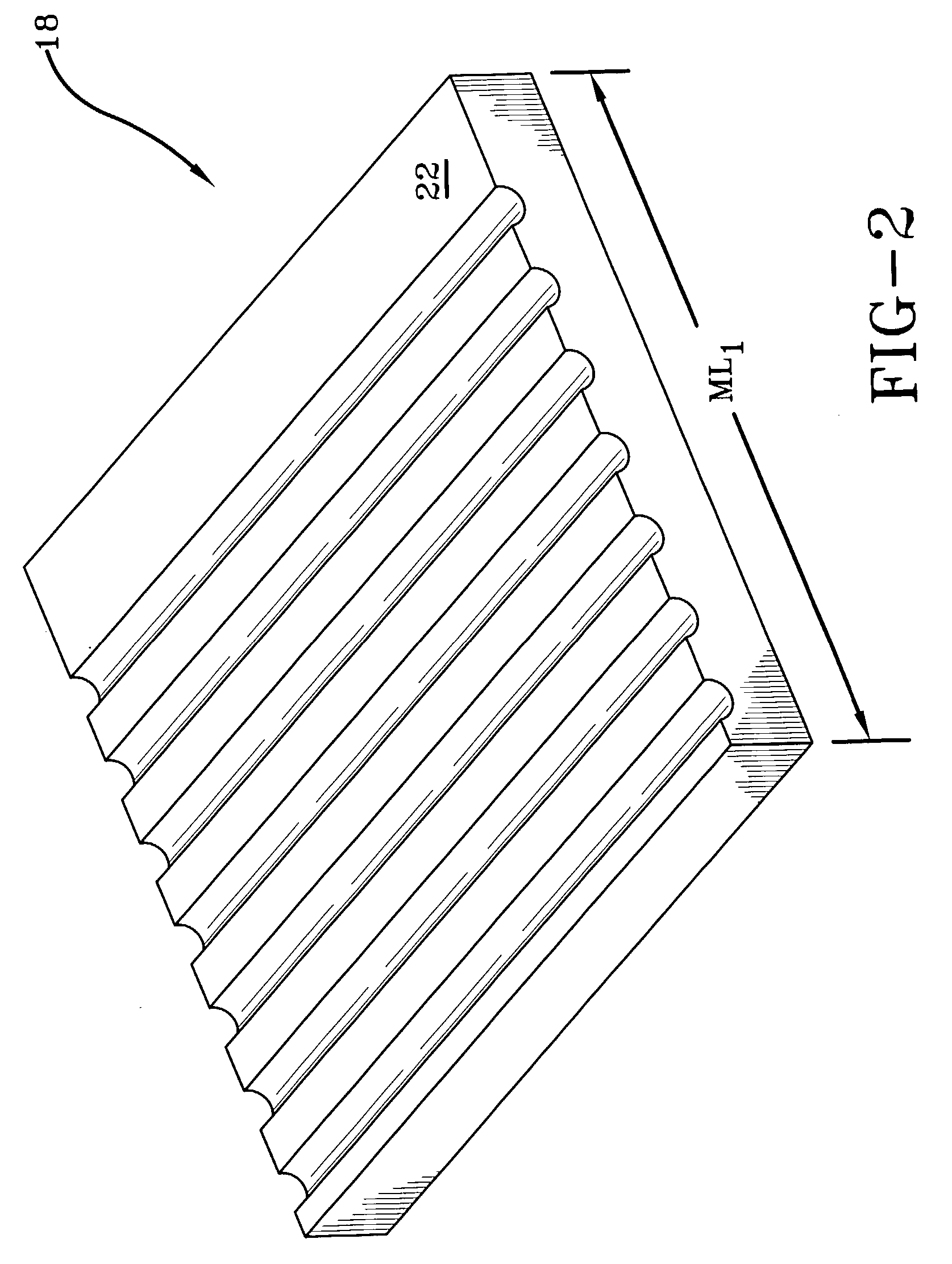
[0080] With reference to FIG. 2, a first mold half 18 is illustrated. With reference to FIG. 1, both the first mold half 18 and the second mold half 20 are illustrated relative to the other portions o...


PUM

PropertyMeasurementUnit
Lengthaaaaaaaaaa
Distanceaaaaaaaaaa
Circumferenceaaaaaaaaaa

Abstract

A method for manufacturing a cured, toothed belt is carried out upon a on a belt-making machine. The method includes incrementally molding sections of the belt with tooth spacing based on an estimated pitch circumference derived from a measured inside circumference, defining and measuring a length of a remaining uncured portion of the belt, the length of the remaining uncured portion of the belt being compared to a design length, a difference between the length of the remaining uncured portion of the belt and the design length being an error; and, adjusting a distance between a centerline of the first drum and the second drum, so that a compensating error is evenly distributed over the remaining uncured portion of the belt. One advantage of this invention is that the cumulative error generated by measuring and curing each section of the belt in an "end to end" manner can be compensated by small adjustments made over a large section of the belt, preventing a large error in the last section of the belt.

Description

I. BACKGROUND OF THE INVENTION[0001] A. Field of Invention[0002] This invention pertains to a method and apparatus for the manufacture of a toothed power transmission belt, and more particularly to a means of correcting the pitch of the belt dynamically, while the belt is being cured.[0003] B. Description of the Related Art[0004] Synchronous power transmission belts transmit motion and power by the engagement of teeth on the belt to teeth on driving and driven sprockets. Commercial tolerances for some of these belts are given in RMA Engineering Standards IP-24 and IP-27. The tolerance on tooth pitch length on such belts ranges from 4444 ppm for miniature belts of 91.44 mm pitch length to 291.5 ppm for large belts of 6860 mm pitch length. IP-27 specifies a pitch length tolerance of +-1.12 mm for a 200 tooth, 14 mm pitch belt, so the average tooth pitch tolerance is .+-.0.0056 mm. The pitch between adjacent teeth must be generally within .+-.0.0254 mm of the nominal pitch, and must be...

Claims


Application Information

Patent Timeline
IPC IPC(8): B29D29/08
CPCB29L2031/7094B29D29/08
Inventor WOOD, DOUGLAS BRUCE
Owner VEYANCE TECH
Learn More