
Method and apparatus for hydrogen production from organic wastes and manure

a technology of organic waste and manure, which is applied in the field of two-phase anaerobic digestion of biodegradable feedstocks, can solve the problems of scum buildup, temperature fluctuations, and limited contact between organic material and bacteria, and achieves the effects of reducing the number of organic wastes, and improving the quality of organic wastes

Inactive Publication Date: 2004-06-17
GAS TECH INST
View PDF16 Cites 35 Cited by
  • Summary
  • Abstract
  • Description
  • Claims
  • Application Information

AI Technical Summary

Benefits of technology

[0014] It is another object of this invention to provide a method and system which provides beneficial disposition of the high-organic wastes generated by farms and industry.

Problems solved by technology

Early designs of sewage digesters attempted to biodegrade sewage sludge for the purposes of sludge volume and odor reduction in an unmixed digester, but they were generally unsuccessful because they failed to provide adequate control of solids inventory, and they developed serious problems such as scum buildup, temperature fluctuations, unequal microbial activity and limited contact between the organic material and the bacteria.
The high water content of these types of organic feedstocks causes washout of feed solids and microorganisms from continuously stirred tank reactors at high feed loadings due to high dilution rates.
Washout of feed solids and microorganisms results in reduced conversion efficiency and unstable digester conditions.
Shorter feed solids retention times in the digester, washout of slow-growing methanogenic bacteria and accumulation of inhibitory acidic fermentation products contribute to low conversion efficiency and reduced methane production.
Anaerobic filter-type digesters are also limited to primarily liquid feedstocks containing less than about 1 percent solids because they become plugged when solids concentration in the digester increases due to higher solids loading or accumulation of solids over longer periods of operation.

Method used


Image

  • Method and apparatus for hydrogen production from organic wastes and manure
  • Method and apparatus for hydrogen production from organic wastes and manure

Examples


Embodiment Construction

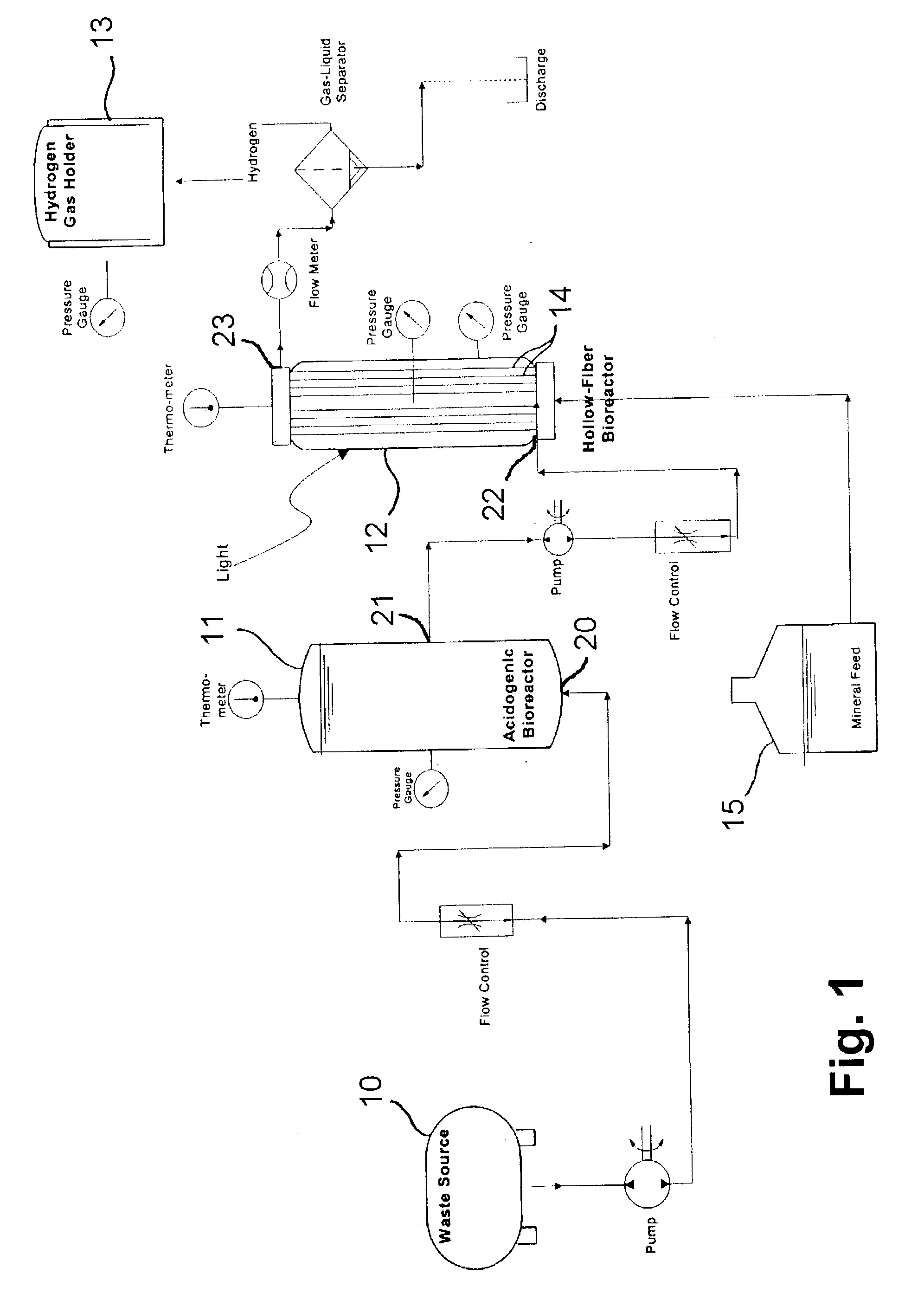
[0020] FIG. 1 is a diagram showing a two stage anaerobic digestion system for performing the method of this invention. The system comprises a first stage anaerobic bioreactor vessel 11 having a feedstock inlet 20 in fluid communication with a waste source 10 and a liquid effluent outlet 21 in fluid communication with liquid effluent inlet of the second stage anaerobic bioreactor vessel 12. In accordance with one embodiment of this invention, both the first stage anaerobic bioreactor and the second stage anaerobic bioreactor are constantly stirred tank reactors.

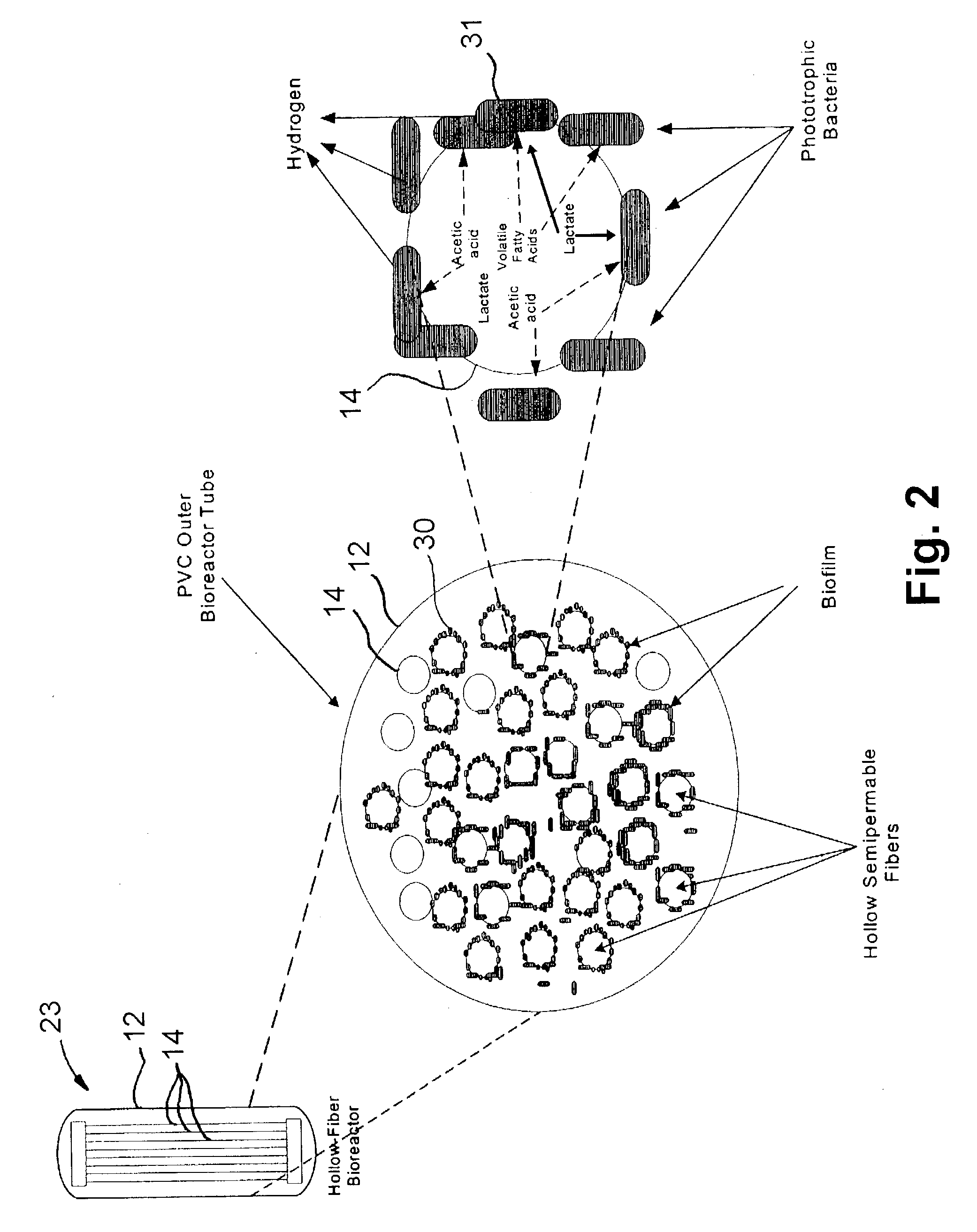
[0021] Second stage anaerobic bioreactor vessel 12 is a photosynthetic bioreactor comprising an outer wall that is light transmissive. In accordance with one embodiment of this invention, the outer wall is transparent; in accordance with another embodiment of this invention, the outer wall is translucent. Disposed within the second stage anaerobic bioreactor vessel 12 is a plurality of hollow semipermeable fibers 14 suitably a...


PUM


Abstract

A method for hydrogen production from biodegradable feedstocks in which a feedstock having at least one biodegradable solid is introduced into a first stage anaerobic bioreactor operating at thermophilic conditions to form a liquid effluent which includes fatty acids. The liquid effluent is transferred through a plurality of hollow semipermeable fibers disposed in a second stage anaerobic bioreactor having a light transmitting wall, which hollow semipermeable fibers have an outer surface coated with a biofilm of photosynthetic bacteria, which photosynthetic bacteria, using the nutrients in the hollow fibers and the incoming light, generates hydrogen.

Description

[0001] 1. Field of the Invention[0002] This invention relates to two-phase anaerobic digestion of biodegradable feedstocks, such as organic wastes and manure. More particularly, this invention relates to a method and apparatus for two-phase anaerobic digestion of organic wastes, such as manure from large animal production, food processing wastes, as well as energy crops, e.g. grasses, corn etc. for producing hydrogen gas for use in energy production in which the second anaerobic digestion phase is carried out in a bioreactor vessel utilizing hollow semipermeable fibers in which the liquid effluent from the first anaerobic phase is transmitted into the hollow semipermeable fibers, which then passes through the semipermeable walls of the fibers for processing by photosynthetic bacterial cultures disposed in the second phase bioreactor vessel and surrounding the fibers. The hydrogen gas generated can be used in conjunction with fuel cell technology to generate electricity on the farms ...

Claims


Application Information

Patent Timeline
IPC IPC(8): C02F3/28C02F3/34C12M1/00C12M1/107C12P3/00
CPCC02F3/2853C02F3/286C02F3/348C02F2103/20C12P3/00C12M21/02C12M21/04C12M25/10C12M29/02C02F2103/32
Inventor PATEREK, JAMES ROBERT
Owner GAS TECH INST
Learn More