
Lighting device and liquid crystal display device

a liquid crystal display and light guide technology, applied in lighting and heating apparatus, instruments, mechanical equipment, etc., can solve the problems of reducing the visibility of the liquid crystal display device, unable to uniformly and brightly illuminate a large area of the display screen, and unable to obtain uniform outgoing

Inactive Publication Date: 2004-05-06
ALPS ALPINE CO LTD
View PDF3 Cites 61 Cited by
  • Summary
  • Abstract
  • Description
  • Claims
  • Application Information

AI Technical Summary

Problems solved by technology

However, in this single light type front light, it is almost impossible to uniformly and brightly illuminate a large area of a display screen having a size of a few inches or greater by combining a thin light guide plate with a single light emitting device.
However, since it is difficult to uniformize the incident light into the light guide plate 112 by the intermediate light guide 113, it is extremely difficult to obtain uniform outgoing light throughout the front side of the light guide plate 112, thus sometimes causing the visibility of the liquid crystal display device to be reduced.
As described above, the demand for the front light using a single light emitting device as a light source is increasing, but a front light capable of uniformly and brightly illuminating a large area is not realized yet.

Method used

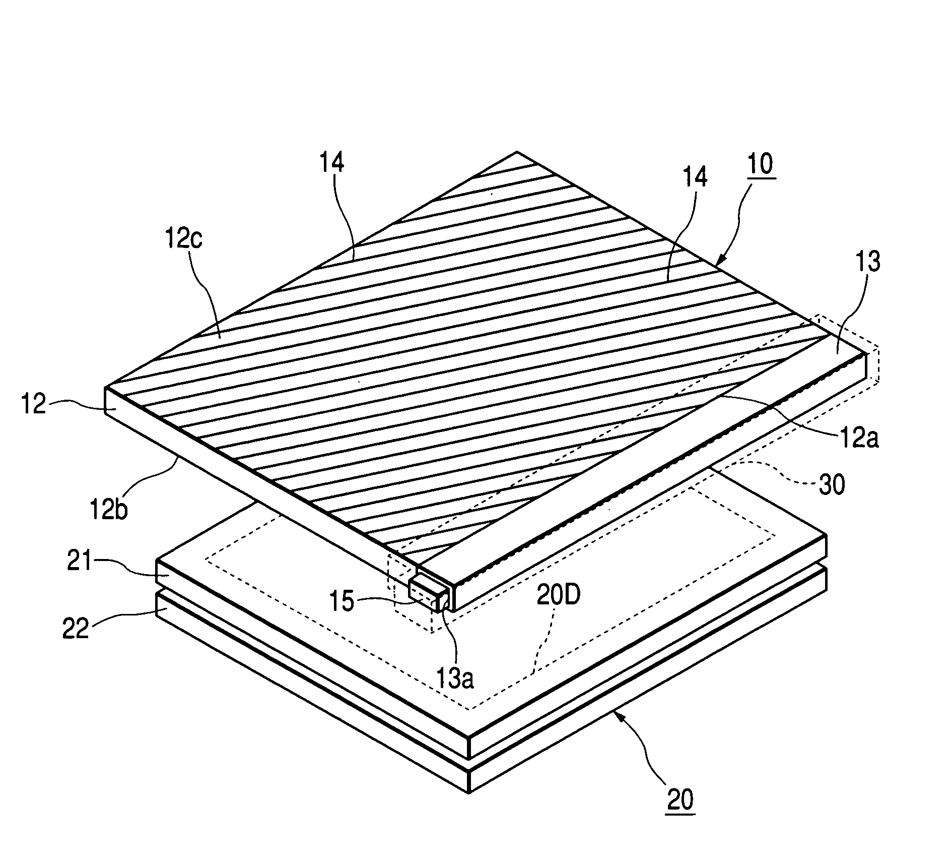
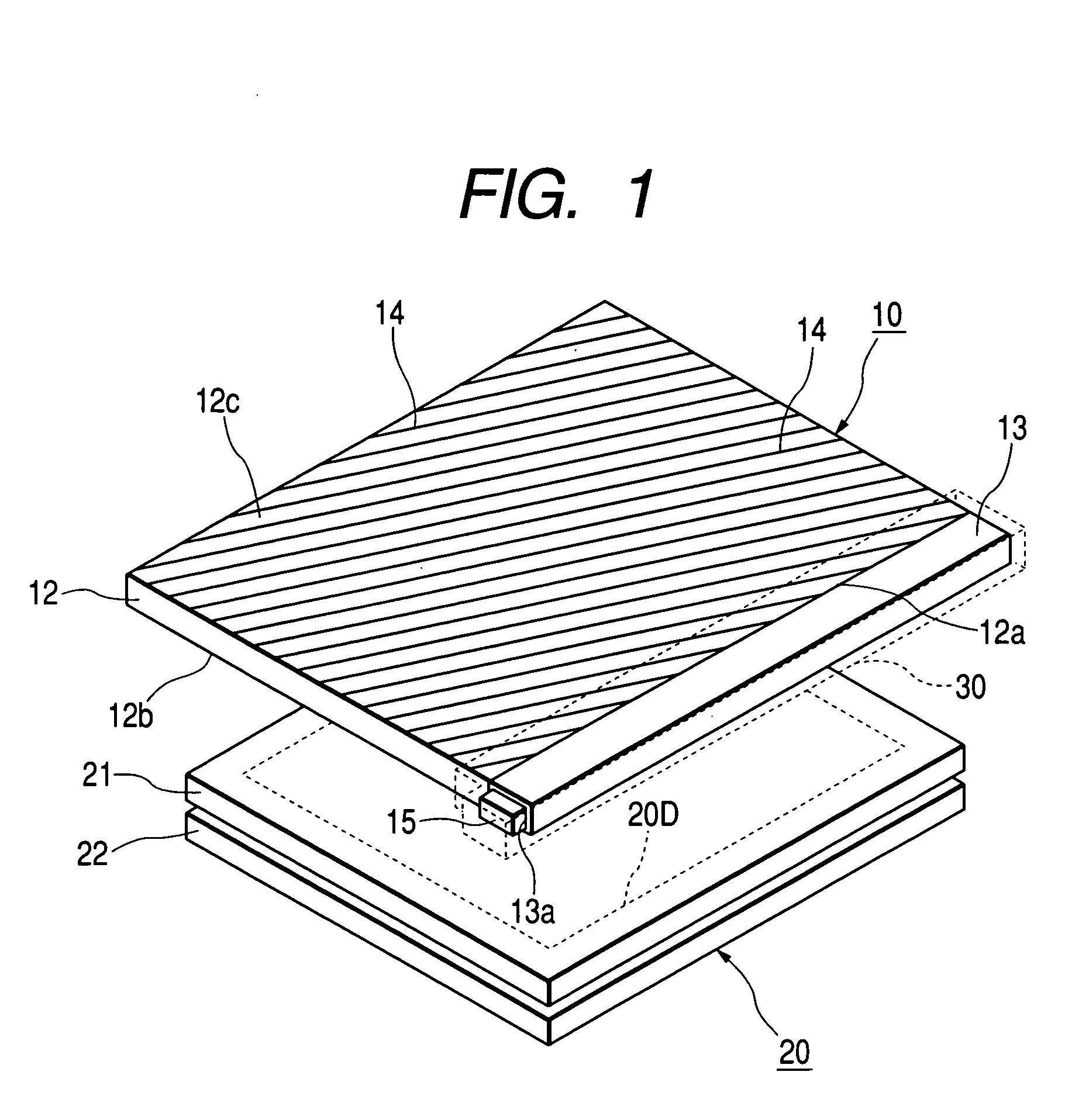

Image

  • Lighting device and liquid crystal display device
  • Lighting device and liquid crystal display device
  • Lighting device and liquid crystal display device

Examples


Embodiment Construction

[0101] Hereafter, the invention will be described more detailedly by examples.

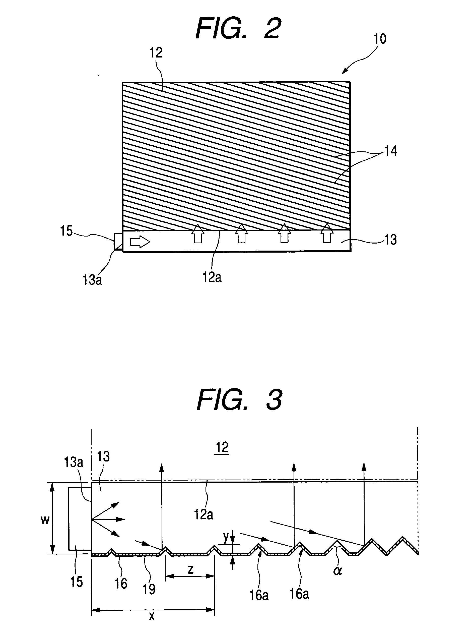
[0102] In the examples, an amount of outgoing light in the longitudinal direction of the intermediate light guide 13 shown in FIG. 3 was optimized, and the distributions of the depth and pitch between the grooves 16a that can obtain a uniform distribution of an amount of outgoing light were derived by calculation. FIGS. 7 and 8 are graphs illustrating examples where the distribution of the depth and the distribution of the pitch between the grooves 16a are optimized, respectively, in the case where the width W of the light guide 13 shown in FIG. 3 was 4.8 mm. FIGS. 9 and 10 depict the case where the width W was 4.0 mm, and FIGS. 11 and 12 depict the case where the width W was 3.0 mm.

[0103] In obtaining the distribution of the depth of the groove and the distribution of the pitch between the grooves by calculation, the dimensions of the intermediate light guide 13 were 68 mm (L).times.3 mm (W).times.0.9 mm ...


PUM

PropertyMeasurementUnit
widthaaaaaaaaaa
angleaaaaaaaaaa
widthaaaaaaaaaa

Abstract

A front light of the invention has a light guide plate, an intermediate light guide disposed along the side end surface, and a light emitting device disposed on an end surface thereof. The pitch between grooves having a wedge shape in cross section formed on a backside of the light guide on the opposite side of the light guide plate is formed so as to be linearly varied with respect to the distance from an end surface disposed with the light emitting device to the groove. The depth of the groove is formed more deeply as the grooves are positioned more apart from the end surface. In the distribution of the depth of the groove with respect to the distance from the end surface to the groove, there are a first area where the depth of the groove is linearly increased with respect to the distance from the end surface disposed with the light emitting device to the groove, and a second area formed apart from the light emitting device more than the first area in which the increasing rate of the depth of the groove with respect to the distance from the end surface is greater than that in the first area.

Description

[0001] 1. Field of the Invention[0002] The present invention relates to a light guide, a lighting device and a liquid crystal display device.[0003] 2. Description of the Related Art[0004] For a front light of a reflective liquid crystal display device, a unit is used which is configured of a light source, an intermediate light guide, a light guide plate and a case for integrally holding them in which the inner side is formed to be reflective.[0005] FIG. 13A is a perspective view illustrating a liquid crystal display device having this configuration, and FIG. 13B is a plan view illustrating the liquid crystal display device shown in FIG. 13A. The liquid crystal display device shown in these drawings is configured of a liquid crystal display unit 120 and a front light 110 disposed on the front side of the liquid crystal panel 120. The detail is not shown in the drawings, however, the liquid crystal display device 120 is a reflective liquid crystal display unit that reflects light inci...

Claims


Application Information

Patent Timeline
Patent Type & Authority Applications(United States)
IPC IPC(8): G02F1/13357F21V8/00F21Y101/02G02B6/00
CPCG02B6/0028G02B6/0038G02F2001/133616G02B6/0061G02B6/0055G02F1/133616
Inventor SUGIURA, TAKURO
Owner ALPS ALPINE CO LTD
Learn More