
Camera that combines the best focused parts from different exposures to an image

Inactive Publication Date: 2004-04-29
AFSENIUS SVEN AKE +1
View PDF20 Cites 146 Cited by
  • Summary
  • Abstract
  • Description
  • Claims
  • Application Information

AI Technical Summary

Benefits of technology

0002] The purpose of the present invention is to accomplish an instrument where hitherto restrictive conditions related to photography are removed more or less. A major such limitation is the practical impossibility to produce photos of high image definition for all ranges. And strictly speaking, it's equally difficult to attain short depths of field, suppressing image detail being outside this interval, such residual detail-blur manifesting another restriction. A third limitation of similar character, is associated with the frequently occurring situation of large intensity variations across a scene, usually in-between light and shade, making it impossible to register bright and dark areas in full detail.
0003] It may be recalled that depth of field for standard photographic lenses depends upon relative ap

Problems solved by technology

A major such limitation is the practical impossibility to produce photos of high image definition for all ranges.
And strictly speaking, it's equally difficult to attain short depths of field, suppressing image detail being outside this interval, such residual detail-blur manifesting another restriction.
A third limitation of similar character, is associated with the frequently occurring situation of large intensity variations across a scene, usually in-between light and shade, making it impossible to register bright and dark areas in full detail.
However a significant stop will also degrade the feasible image resolution, due to wave properties of light.
Another consequence of stopping down an objective is loss of light which however may become less conclusive due to high sensitivity characteristics of modem electronic pixel-oriented image registration.

Method used


Image

  • Camera that combines the best focused parts from different exposures to an image
  • Camera that combines the best focused parts from different exposures to an image
  • Camera that combines the best focused parts from different exposures to an image

Examples


Embodiment Construction

OF EMBODIMENT & APPLICATIONS IN DETAIL

[0020] The present invention applies to an electrooptical instrument with capacity to eliminate some of the more fundamental restrictions which have always prevailed within photography. Most examples exemplifying the invention here aim at depth of field-improvements. However, other fundamental limitations may be remedied in an essentially similar or equivalent way.

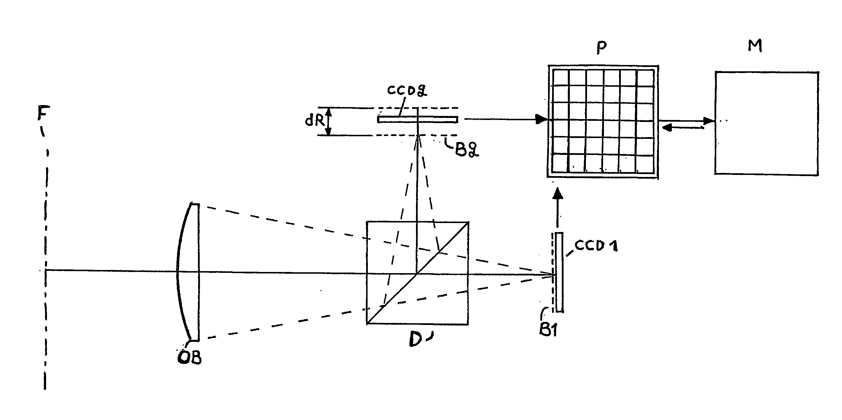
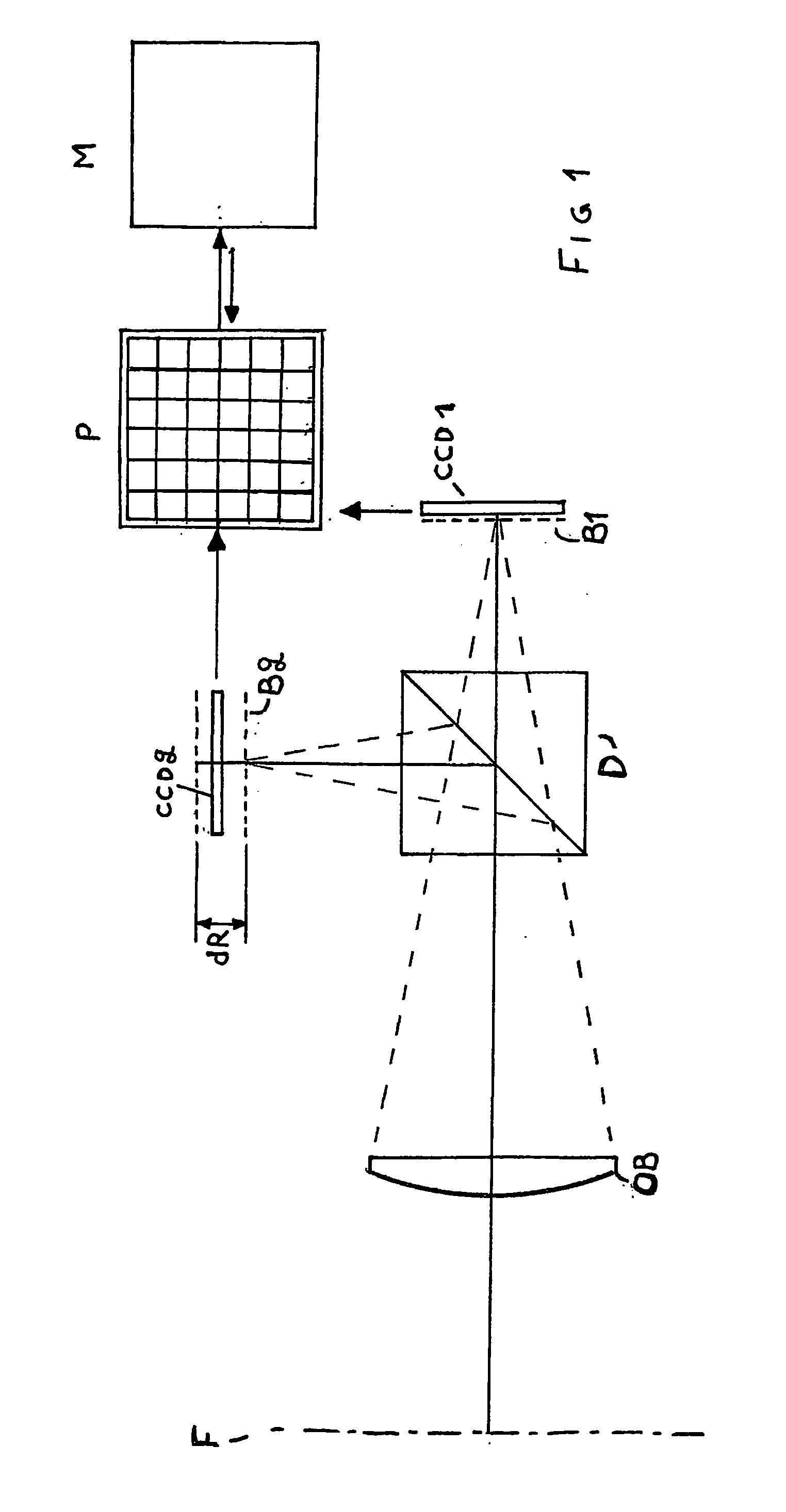
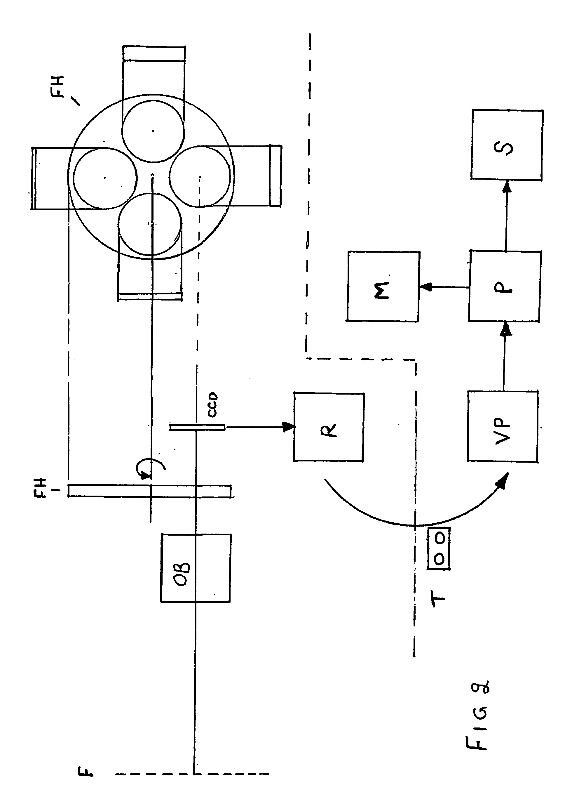
[0021] It's an instrument with capacity to measure image definition, optically projecting a scene upon an electronic detector, registering images / frames in different states of focus, and all subdivided into smaller parts. That part-picture having best image definition is chosen and merged into a resultant final image, being saved in an electronic memory and / or being presented as a picture on paper or an image screen.

[0022] The invention, according to various configurations in the characteristic parts of relevant claims presented here, is thereby solving the problem to obtain high image...


PUM


Abstract

The object of the present invention is to eliminate hitherto restrictive conditions related to photography, like when attempting to register pictures with infinite depth of field, more or less, or attempt full detail-reproduction of light and shade. This is, according to the present invention, accomplished by making several recordings with differing states of focus or exposure, the images registered being similarly subdivided into smaller image-parts and a resultant image bing produced by selecting those image-parts from each set, being most suitable. Optimal image definition of an image-part can for instance be assessed by contrast-measurement techniques or separate range-finding with a laser. An analogous optimal representation of image detail can also be achieved.

Description

[0001] The present invention refers to a camera with an image registration device in its image plane, preferably an electronic one like a CCD sensor. To be more specific, it's an electronic instrument with an objective lens, a pixel-oriented image detector with entrance surface, an electronic image memory for saving image information originating in the same detector and an automatic focusing device, according to a preferred mode of operation. The invention is furthermore referring to the corresponding methods, some of them applicable for (emulsion-) film cameras as well, however with a subsequent image process.PURPOSE OF THE INVENTION[0002] The purpose of the present invention is to accomplish an instrument where hitherto restrictive conditions related to photography are removed more or less. A major such limitation is the practical impossibility to produce photos of high image definition for all ranges. And strictly speaking, it's equally difficult to attain short depths of field, ...

Claims


Application Information

Patent Timeline
IPC IPC(8): G02B7/36H04N5/232
CPCG02B7/36H04N5/2356H04N5/23212H04N23/671H04N23/743
Inventor AFSENIUS, SVEN-AKEHAGENE, JON KRISTIAN
Owner AFSENIUS SVEN AKE
Learn More