Eureka AIR delivers breakthrough ideas for toughest innovation challenges, trusted by R&D personnel around the world.

Device manufacturing apparatus and method, and driving method for device manufacturing apparatus

a manufacturing apparatus and manufacturing technology, applied in the direction of identification means, instruments, liquid handling, etc., can solve the problems of deterioration in workability and increase in manufacturing costs

Inactive Publication Date: 2004-04-29
KATEEVA
View PDF2 Cites 10 Cited by
  • Summary
  • Abstract
  • Description
  • Claims
  • Application Information

AI Technical Summary

Benefits of technology

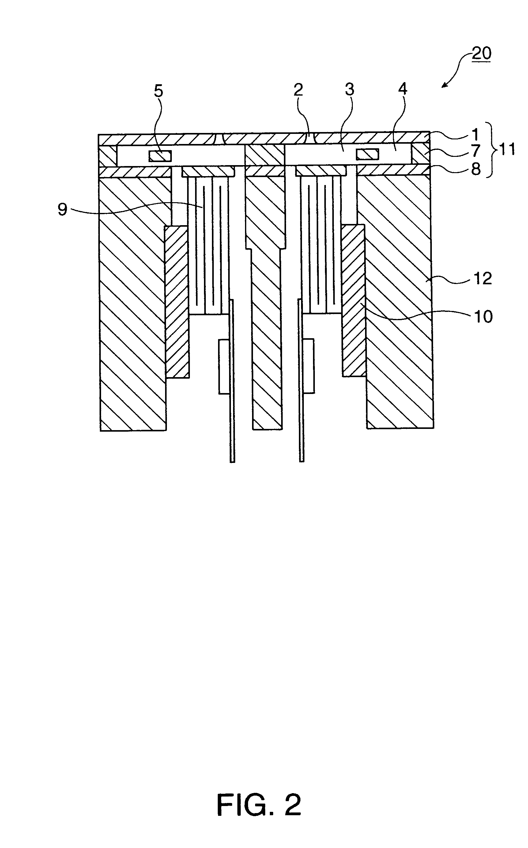
[0013] Therefore, the vibration of the meniscus of the nozzle opening corresponding to the pressure generation chamber can be effectively suppressed, thus realizing stable ejection.
[0061] In this instance, the droplet ejecting device according to the present invention includes an ink-jet device having an inkjet head (droplet ejecting head). The ink-jet head of the ink-jet device can quantitatively eject a liquid material according to an ink-jet technology. For example, the device can quantitatively and intermittently drop a liquid material (fluid) of, for example, 1 to 300 nanograms. Since the inkjet technology is used as the device manufacturing method, a device can be formed in a predetermined pattern with low-cost equipment.

Problems solved by technology

These methods need various processes such as film formation, photolithography, and development, resulting in a deterioration in the workability and an increase in the manufacturing cost.

Method used


Image

  • Device manufacturing apparatus and method, and driving method for device manufacturing apparatus
  • Device manufacturing apparatus and method, and driving method for device manufacturing apparatus
  • Device manufacturing apparatus and method, and driving method for device manufacturing apparatus

Examples


Embodiment Construction

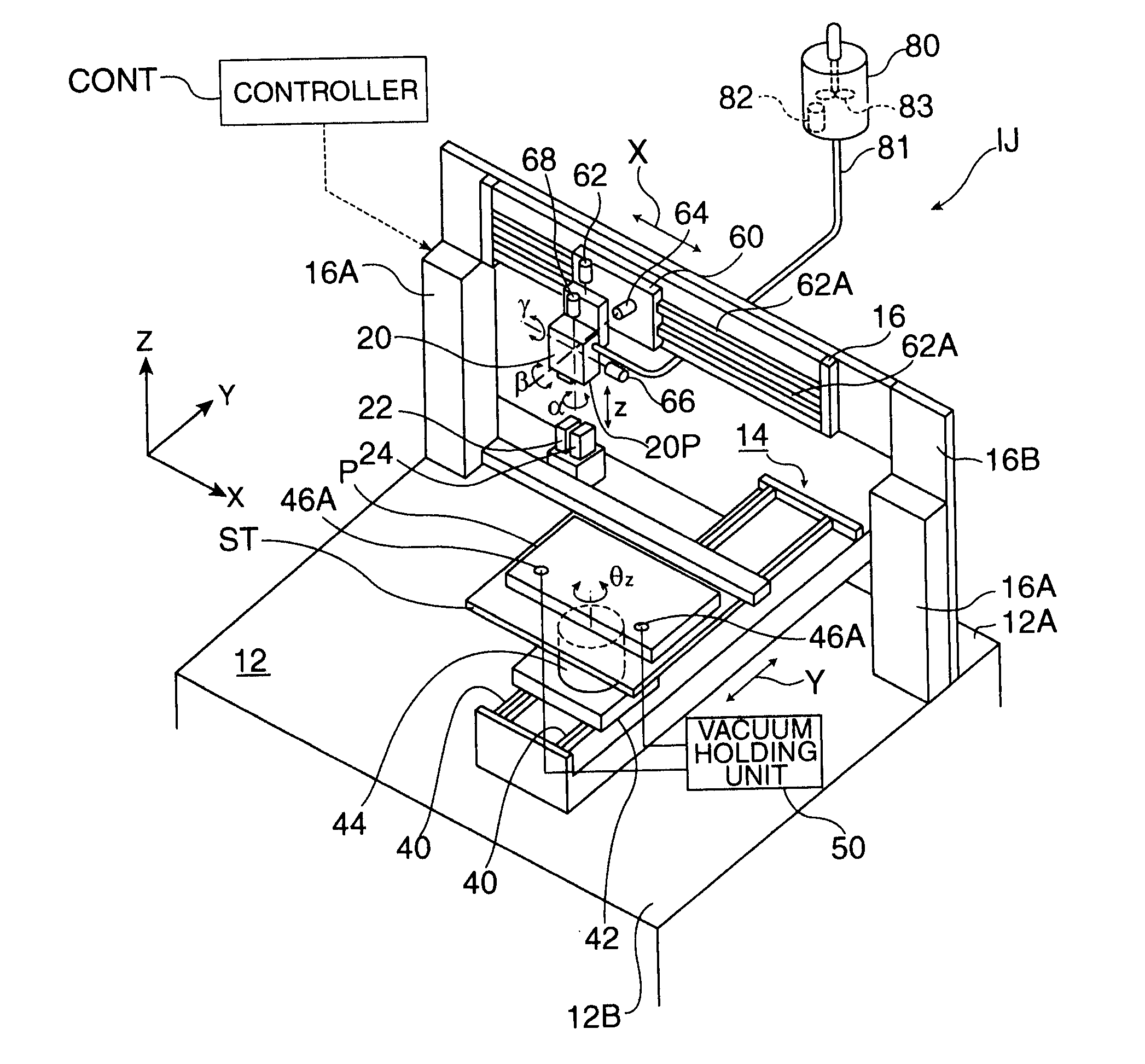
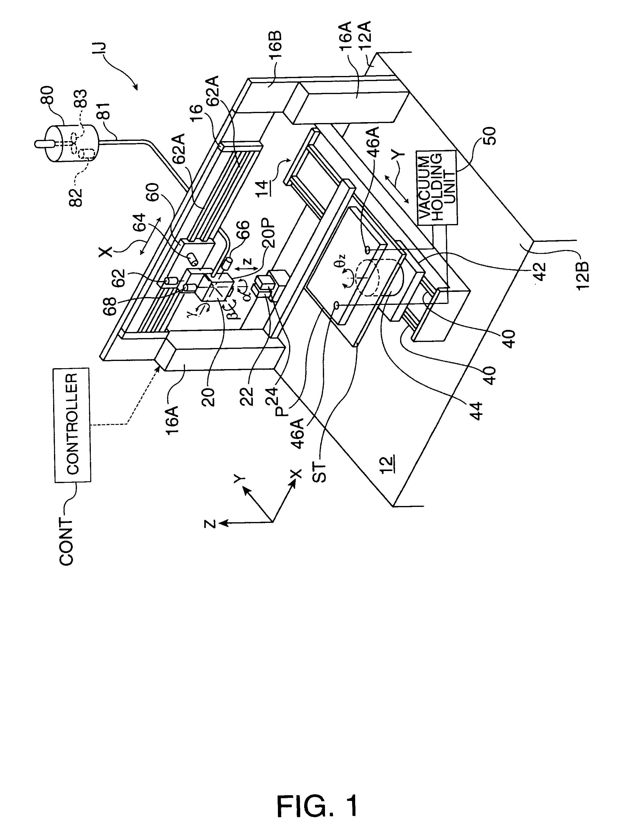
[0067] A device manufacturing apparatus and method, and a method for driving the device manufacturing apparatus according to the present invention will now be described hereinbelow with reference to the drawings. FIG. 1 is a schematic perspective view showing an ink-jet device serving as a droplet ejecting device constituting a device manufacturing apparatus according to the present invention.

[0068] Referring to FIG. 1, an ink-jet device (droplet ejecting device) IJ functions as a film forming device in which a liquid material can be set on a substrate P. The device U comprises a base 12, a stage ST which is disposed above the base 12 and which supports the substrate P, a first shifting unit (shifter) 14 which is interposed between the base 12 and the stage ST and which movably supports the stage ST, an ink-jet head (droplet ejecting unit) 20 which can quantitatively eject (drop) an ink (a liquid material or a fluid) including a predetermined material to the substrate P supported by...


PUM


Abstract

[Object] To provide a device manufacturing apparatus in which a device can be precisely manufactured by stably ejecting a predetermined amount of droplets when the device is manufactured using a droplet ejecting device. [Solving Means] A pressure generation chamber 3 has a Helmholtz resonance frequency of a period TH. A driving signal includes a first signal element to cause the pressure generation chamber 3 to expand, a second signal element to cause the expanded pressure generation chamber 3 to contract, and a third signal element to cause the pressure generation chamber 3 to expand to its original state, which is held before the first signal element is output, after ejection of a droplet. The time which elapses between the beginning of output of the first signal element and the beginning of output of the second signal element, and the time which elapses between the beginning of output of the second signal element and the beginning of output of the third signal element are set to be substantially equivalent to the period TH. The sum of the amplitude of the first signal element and that of the third signal element is set to be substantially equivalent to the amplitude of the second signal element.

Description

[0001] 1. Technical Field of the Invention[0002] The present invention relates to a device manufacturing apparatus and method for manufacturing a device using a droplet ejecting device and a method for driving the device manufacturing apparatus.[0003] 2. Description of the Related Art[0004] Hitherto, color filters have been used in liquid crystal displays. The color filter is formed so as to be integrated with a liquid crystal display and functions to improve image quality and to give the primary colors to respective pixels. Methods for manufacturing the color filter include: a method for irradiating a film, coated with a photosensitive resin, with light through a photomask to cure irradiated portions, removing unirradiated portions of the film through development to form a pattern, and then coloring the patterned film (coloring method); and photolithography whereby compositions formed by dispersing red, green, and blue colorants into respective photosensitive resins are sequentiall...

Claims


Application Information

Patent Timeline
IPC IPC(8): B41J2/01B05C5/00B05D1/26B41J2/045B41J2/05B41J2/055G02B5/20G02F1/13G02F1/1335G09F9/00
CPCB41J2/04506B41J2/04528B41J2/04588B41J2/0458B41J2/04581B41J2/04563G02F1/13
Inventor KIGUCHI, HIROSHI
Owner KATEEVA
Why Eureka
Eureka Blog
Learn More