
Electron gun assembly for cathode ray tube

Inactive Publication Date: 2004-04-01
SAMSUNG SDI CO LTD
View PDF4 Cites 0 Cited by
  • Summary
  • Abstract
  • Description
  • Claims
  • Application Information

AI Technical Summary

Problems solved by technology

Consequently, with the electric current range of 2 mA or less, the spot size of the electron beams is increased while deteriorating the resolution, resulting in unclear display images.
However, this reduction makes the area of electron emission for the cathode so small that the life span of the electron gun with the cathode is reduced.
However, with the above structure, as the CRT neck portion mounting the electron gun thereon is limited in its diameter, there is a limit in mechanically enlarging the opening diameter of the fourth and the fifth electrodes forming the main-focus lens.
Accordingly, as the opening diameter of the fourth and the fifth electrodes is established in a predetermined manner, it is difficult to achieve the desired electrode capacity in an effective manner.

Method used


Image

  • Electron gun assembly for cathode ray tube
  • Electron gun assembly for cathode ray tube
  • Electron gun assembly for cathode ray tube

Examples


Embodiment Construction

.25 0.20 2.00 0.20 Comparative 0.30 0.40 -- --Example

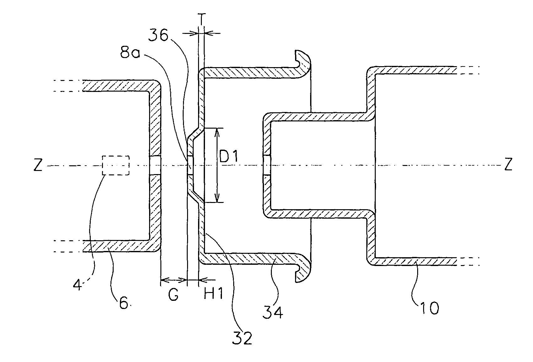
[0053] It can be seen from FIG. 5 that with the electron gun according to the prior art, the crossover point (COP) of the electron beams focused at the triode portion by way of the pre-focus lens is positioned at the location distant from cathode 1 by 0.58 mm. The electron beams passing the crossover point (COP) proceed toward third electrode 7 while being diffused at an angle of lower degrees.

[0054] In contrast, it can be seen from FIG. 6 that with the electron gun according to the embodiment of the present invention, the crossover point (COP) of the electron beams focused at the triode portion by way of a pre-focus lens is positioned at the location distant from cathode 4 by 0.42 mm. The electron beams passing the crossover point (COP) proceed toward the third electrode 10 while being diffused at an angle of higher degrees.

[0055] As described above, the crossover point of the electron beams with electron gun 2 according to the e...


PUM


Abstract

An electron gun for a monochrome cathode ray tube to be used in a projection display device includes a cathode for emitting thermal electrons, and first and second electrodes forming a triode portion together with the cathode. A third electrode is adjacent the second electrode. A fourth electrode is adjacent the third electrode to receive a focus voltage. A fifth electrode partially surrounds the fourth electrode while being adjacent the fourth electrode to receive an anode voltage together with the third electrode. The second electrode has a bottom portion with a stepped portion surrounding a hole for guiding the electron beams while being protruded toward the first electrode, and a sidewall portion extended from the periphery of the bottom portion toward the third electrode. The first and the second electrodes are structured to satisfy the following condition: 0.54<=T / G<=1.50 wherein T(mm) indicates the thickness of the bottom portion of the second electrode, and G(mm) indicates the distance between the first and the second electrodes.

Description

[0001] This application claims priority to and the benefit of Korea Patent Application No. 2002-0036668 filed on Jun. 28, 2002 in the Korean Intellectual Property Office, the entire disclosure of which is incorporated herein by reference.[0002] (a) Field of the Invention[0003] The present invention relates to an electron gun assembly for a cathode ray tube (CRT) and, more particularly, to an electron gun well adapted for a monochrome CRT to be mounted within a projection display device to realize a monochrome image.[0004] (b) Description of the Related Art[0005] Generally, a CRT-based projection display device mainly has three monochrome CRTs for realizing red (R), green (G) and blue (B) monochrome images, and an optical system for amplifying the monochrome images made at the three CRTs and projecting the amplified images to a projection screen to produce color images.[0006] As the monochrome CRT scans the display screen with one stream of electron beams, and the respective monochro...

Claims


Application Information

Patent Timeline
IPC IPC(8): H01J29/48
CPCH01J29/48
Inventor KIM, YOO-SEON
Owner SAMSUNG SDI CO LTD
Learn More