
Deployable inflatable boom and methods for packaging and deploying a deployable inflatable boom

a technology of deployable inflatable boom and deployable inflatable boom, which is applied in the field of deployable structures, can solve the problems of prone to failure of the boom, stress and wear along the creases of the boom, and limited cargo space of the rocket and shuttl

Inactive Publication Date: 2004-03-11
LGARDE
View PDF0 Cites 35 Cited by
  • Summary
  • Abstract
  • Description
  • Claims
  • Application Information

AI Technical Summary

Benefits of technology

[0011] The preferred embodiments of the present boom and methods for packaging and deploying a boom have several features, no single one of which is solely responsible for their desirable attributes. Without limiting the scope of this boom and methods as expressed by the claims that follow, their more prominent features will now be discussed briefly. After considering this discussion, and particularly after reading the section entitled "Detailed Description of the Preferred Embodiments," one will understand how the features of the preferred embodiments provide advantages, which include high packing density, controlled and predictable deployment, easy attachment of apparatus, such as a solar sail, high stiffness and strength, including high buckling strength, for minimum weight, easy packaging of apparatus together with the boom, sails can be attached to the boom using a following load that avoids high bending moments, capability to support very large structures, higher natural frequency than cylindrical boom of same radius, and minimum gas path length for more effective pre-launch venting.

Problems solved by technology

Further, rockets and shuttles have limited cargo space.
Accordion folding, however, creates stress and wear along the creases in the boom.
The stretching weakens the boom at the creases, and makes the boom prone to fail during or after inflation.
Boom failure typically prevents proper functioning of apparatus that was to be supported by the boom.
Since space structures are often deployed aboard unmanned spacecraft, repairs to failed booms and malfunctioning apparatus are often impossible or too costly.
Thus, failed booms can cause multi-million dollar spacecraft to be abandoned and left floating in space.
Stress and wear caused by accordion folding also complicates testing for booms.
During testing, booms are typically packaged, deployed, deflated, and repackaged multiple times. The repeated folding and unfolding increases the stress and wear on the boom, thereby increasing the likelihood that the boom will fail during testing and prevent an accurate assessment of the boom's capability to perform as desired.
Accordion folding also causes booms to deploy in an unpredictable fashion due to the effects of small inflation transients and friction between parts of the deploying boom.
These effects can cause sudden changes in the deployment behavior of a boom or large gyrations in the movement of the deploying boom end.
The boom may damage or become caught upon neighboring structures if it does not deploy as desired.
Thus, even a miniscule amount of gas left inside the boom during packaging can produce high pressure within the boom after it is launched into space.
This substantial length coupled with friction between contacting inner surfaces of the boom causes small pockets of gas to collect near the folds of the packaged boom.
When the boom is launched into space, this residual gas further exacerbates the problem of uncontrolled and sudden partial deployment of the boom.
The accordion-fold method of packaging a boom is also not amenable for booms that are to be used as a spar to support a membrane structure, such as a solar sail, a shade, or a reflecting surface.
This packaging is very complex, and subjects the membrane to a high probability of damage during the folding and unfolding processes.

Method used


Image

  • Deployable inflatable boom and methods for packaging and deploying a deployable inflatable boom
  • Deployable inflatable boom and methods for packaging and deploying a deployable inflatable boom
  • Deployable inflatable boom and methods for packaging and deploying a deployable inflatable boom

Examples


Embodiment Construction

Background of Invention

[0001]

Field of the Invention

[0002] The present invention relates to deployable structures. More particularly, the present deployable inflatable boom and methods for packaging and deploying a deployable inflatable boom provide controlled and predictable deployment behavior.

Description of the Related Art

[0003] Structures for use in space must be packaged, loaded into a rocket or shuttle, and launched into space. The cost of launching items into Earth orbit can exceed $10,000 per kilogram. Thus, any structure to be used in space is ideally as lightweight as possible. Further, rockets and shuttles have limited cargo space. Thus, many structures for use in space are designed to be collapsible so that they occupy little storage space relative to their deployed size. Once in space, the structures deploy to their usable configuration.

[0004] Inflatable structures offer the dual advantages of a compact packaged configuration and light weight, making them ideal for use i...


PUM


Abstract

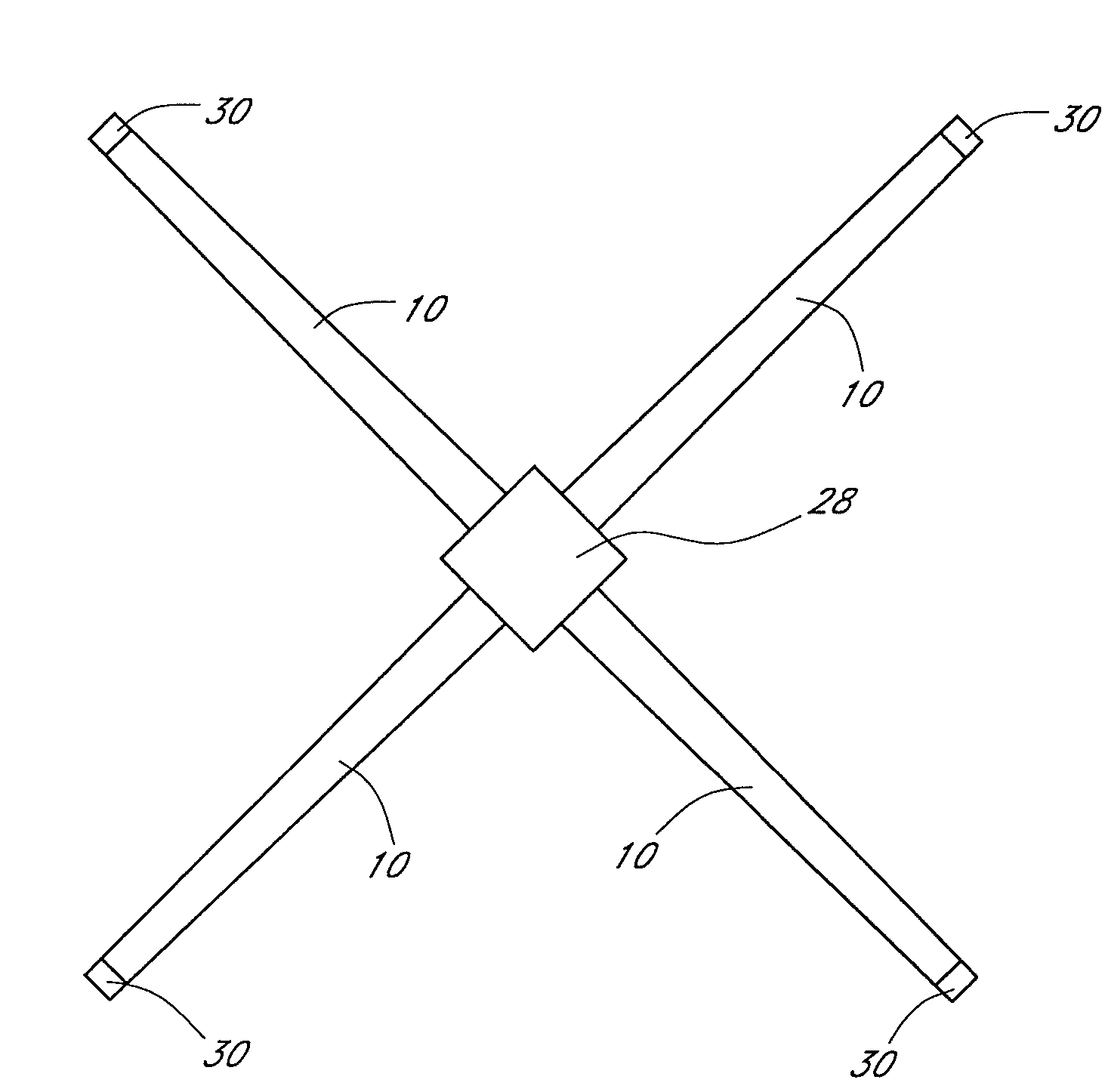
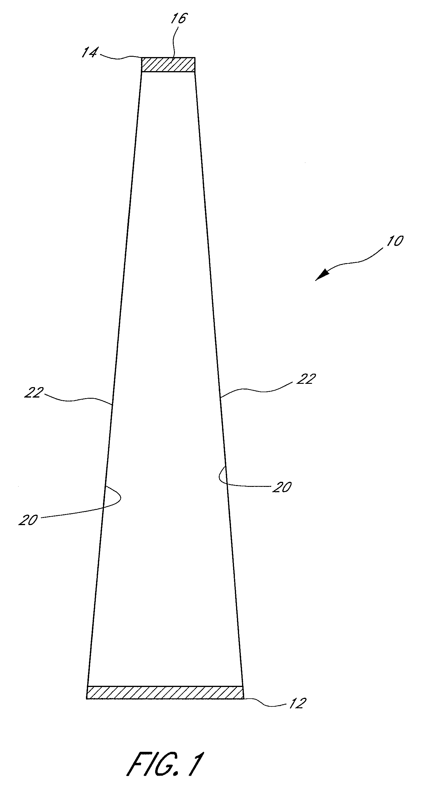
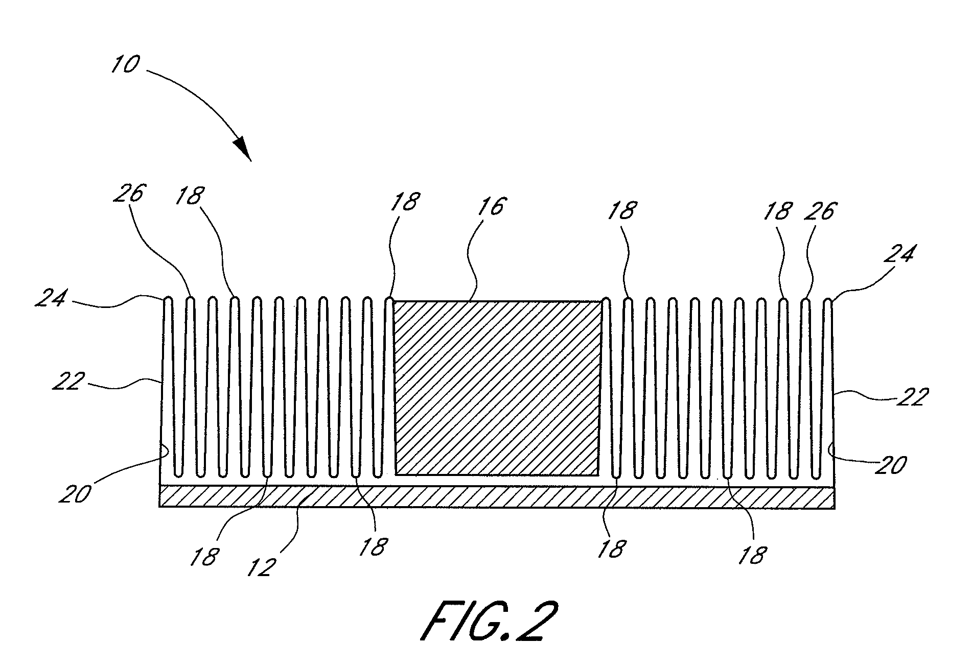
Abstract of the Disclosure An inflatable boom for space applications, and a methods of folding and deploying a boom are disclosed. The boom comprises a membrane having a substantially tapered cylindrical shape. A wide end of the membrane is attached to a base, and a narrow end of the membrane is attached to a mandrel. The method of folding a boom comprises forming a plurality of ring-shaped folds in the boom membrane. The method of deploying a boom comprises increasing a gas pressure inside the boom and repeatedly unfolding the outer-most ring fold to increase the length of the boom.

Description

Detailed Description of the InventionBackground of Invention[0001]Field of the Invention[0002] The present invention relates to deployable structures. More particularly, the present deployable inflatable boom and methods for packaging and deploying a deployable inflatable boom provide controlled and predictable deployment behavior.Description of the Related Art[0003] Structures for use in space must be packaged, loaded into a rocket or shuttle, and launched into space. The cost of launching items into Earth orbit can exceed $10,000 per kilogram. Thus, any structure to be used in space is ideally as lightweight as possible. Further, rockets and shuttles have limited cargo space. Thus, many structures for use in space are designed to be collapsible so that they occupy little storage space relative to their deployed size. Once in space, the structures deploy to their usable configuration.[0004] Inflatable structures offer the dual advantages of a compact packaged configuration and ligh...

Claims


Application Information

Patent Timeline
Patent Type & Authority Applications(United States)
IPC IPC(8): B64G1/22
CPCB64G2001/224B64G1/222B64G1/2227
Inventor VEAL, GORDONPALISOC, ARTHURDERBES, WILLIAM
Owner LGARDE
Learn More