
Devices for intrabody delivery of molecules and systems and methods utilizing same

a technology of intrabody delivery and molecules, applied in the direction of pharmaceutical delivery mechanism, generator/motor, medical preparations, etc., can solve the problems of unfavorable cytotoxic effects at tissue regions, complex and frequent breakdown, and inability to accurately and control the delivery of drugs

Inactive Publication Date: 2004-02-19
REMON MEDICAL TECH
View PDF3 Cites 112 Cited by
  • Summary
  • Abstract
  • Description
  • Claims
  • Application Information

AI Technical Summary

Problems solved by technology

Localized drug delivery is oftentimes preferred since it traverses limitations associated with systemic drug delivery including rapid drug inactivation and / or ineffectual drug concentrations at the site of treatment.
In addition, in some cases, systemic drug delivery can lead to undesired cytotoxic effects at tissue regions other than that to be treated.
Although these devices enable localized drug delivery, their relatively simple design is limited in that it does not enable accurate and controlled delivery of the drug.
Since such devices include miniature power-driven mechanical parts which are required to operate in the body, i.e., they must retract, dispense, or pump, they are complicated and subject to frequent breakdowns.
Moreover, due to complexity and size restrictions, they are unsuitable for delivery of more than a few drugs or drug mixtures at a time.
Although the microchip device described by Santini, Jr., et al. presents substantial improvements over other prior art devices, it suffers from several inherent limitations which will be described in detail hereinbelow.
The use of RF activation is disadvantageous since RF signals are, at least in part, absorbed by body tissues and are directionally limited by bulky unidirectional antennas used for reception.

Method used


Image

  • Devices for intrabody delivery of molecules and systems and methods utilizing same
  • Devices for intrabody delivery of molecules and systems and methods utilizing same
  • Devices for intrabody delivery of molecules and systems and methods utilizing same

Examples


Embodiment Construction

Acoustic Switch Circuitry and Function

[0118] Referring again to the drawings, FIG. 8, illustrates an example of circuitry and components employed by an acoustic switch 200 which is utilizable by the device of the present invention.

[0119] Switch 200 includes a piezoelectric transducer, or other acoustic transducer such the acoustic transducer described hereinabove (not shown, but connectable at locations piezo+ and piezo-), a plurality of MOSFET transistors (Q1-Q4) and resistors (R1-R4), and switch S1.

[0120] In the switch's "sleep" mode, all of the MOSFET transistors (Q1-Q4) are in an off state. To maintain the off state, the gates of the transistors are biased by pull-up and pull-down resistors. The gates of N-channel transistors (Q1, Q3 & Q4) are biased to ground and the gate of P-channel transistor Q2 is biased to +3V. During this quiescent stage, switch S1 is closed and no current flows through the circuit.

[0121] Therefore, although an energy storage device (not shown, but couple...


PUM


Abstract

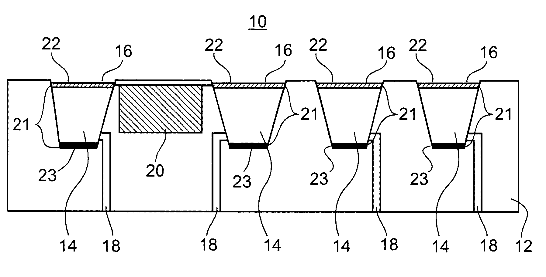
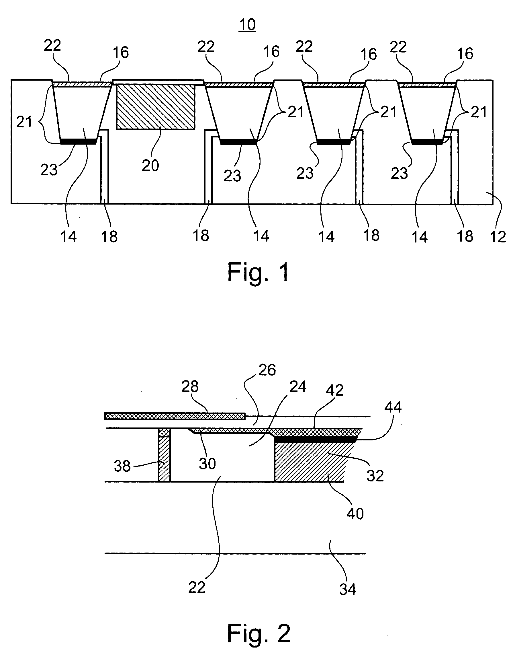
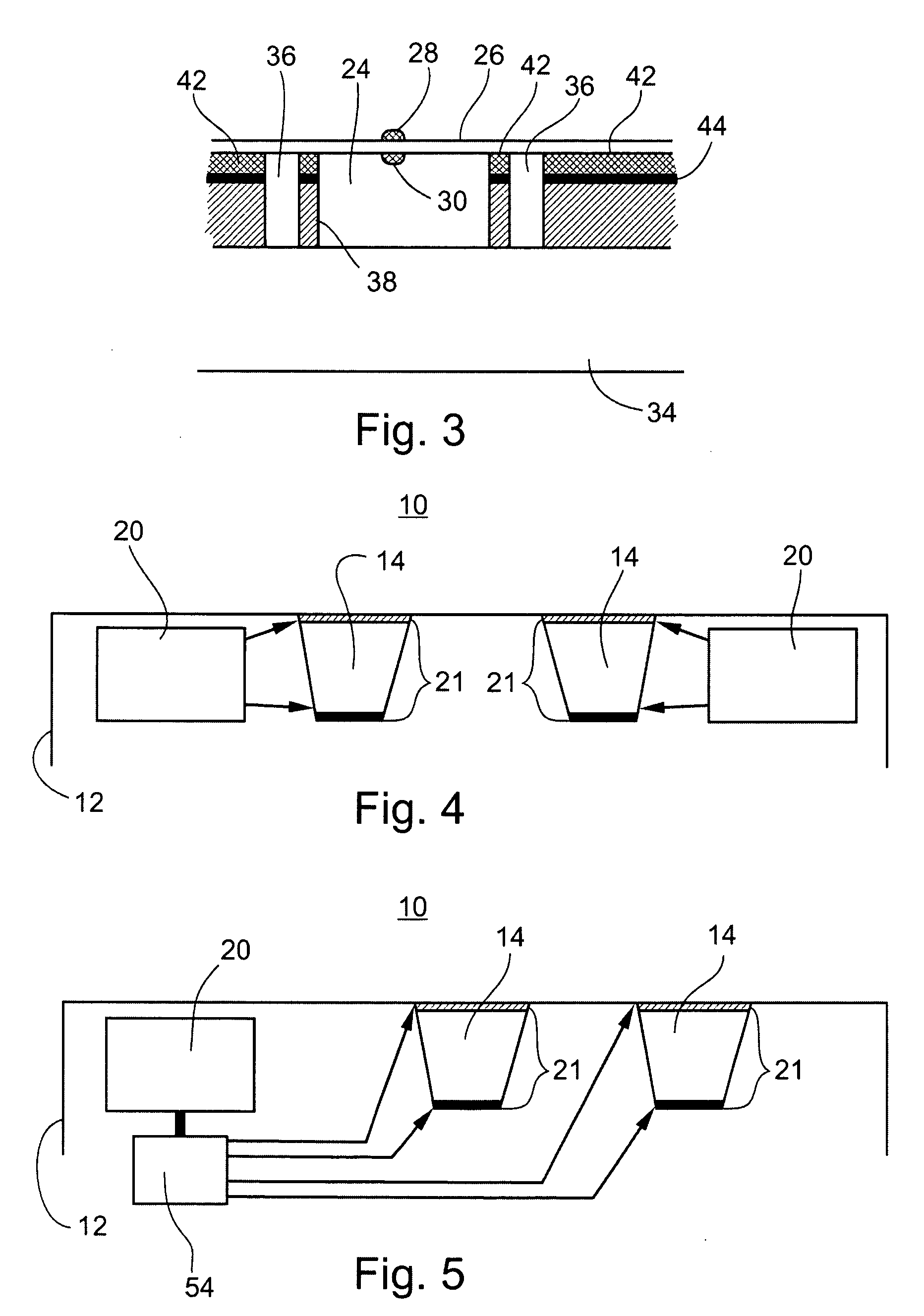
A device for controlled release of molecules is provided. The device including: (a) a device body having at least one reservoir therein for containing the molecules, the at least one reservoir being formed with a barrier impermeable to the molecules thereby preventing release thereof from the at least one reservoir; and (b) at least one acoustic transducer being attached to, or forming a part of, the device body, the at least one acoustic transducer being for converting an acoustic signal received thereby into an electrical signal, the electrical signal leading to barrier permeabilization and therefore release of the molecules from the at least one reservoir.

Description

[0001] This Application is a continuation of co-pending U.S. application Ser. No. 09 / 930,455, filed Aug. 16, 2001. This Application also claims priority of co-pending U.S. application Ser. No. 10 / 235,968, filed Sep. 6, 2002, which is a continuation of U.S. application Ser. No. 09 / 691,887, filed Oct. 20, 2000, now U.S. Pat. No. 6,504,286, which is a continuation of U.S. application Ser. No. 09 / 000,553, filed Dec. 30, 1997, now U.S. Pat. No. 6,140,740, all of which are incorporated by reference herein in their entireties.FIELD AND BACKGROUND OF THE INVENTION[0002] The present invention relates to a device for intrabody delivery of molecules, to a method and system of utilizing same and to a method of fabricating same. More particularly, embodiments of the present invention relate to a drug delivery device which utilizes an acoustic transducer for generating an electrical activation signal from an acoustic signal received thereby.[0003] The efficacy of drug treatment is oftentimes depe...

Claims


Application Information

Patent Timeline
Patent Type & Authority Applications(United States)
IPC IPC(8): A61K9/00A61K9/22
CPCA61K9/0009A61K9/0097A61K9/0024H10N30/80
Inventor PENNER, AVIDORON, EYAL
Owner REMON MEDICAL TECH
Learn More