
Magnetic logic elements

a logic element and magnetic field technology, applied in the field of logic elements, can solve the problems of increasing the difficulty of exponential growth, affecting the stability of the system,

Inactive Publication Date: 2004-02-12
HORST SIEDLE GMBH & CO KG
View PDF5 Cites 9 Cited by
  • Summary
  • Abstract
  • Description
  • Claims
  • Application Information

AI Technical Summary

Problems solved by technology

Fundamental physical phenomena associated with small particles make this exponential growth increasingly difficult to sustain.
Such spontaneous creation is undesirable as it leads to an erroneous logic state being generated.
An ideal magnetic logic device would have a propagation field very close to zero (solitons propagate completely freely without any resistance to motion) and a very high nucleation field (errors are very difficult to create).
Whilst the field necessary to propagate solitons in a straight line is relatively small, changes in direction, junctions, and logic gates will result in poorer coupling between adjacent solitons.
The resulting energy discontinuity necessitates higher propagation fields, reducing the gap between the propagation and the nucleation fields, and leading to the problems above described.
Beaneath 5 mm, material inconsistencies and production difficulties are likely to be greater, above 10 nm power demands will rise.
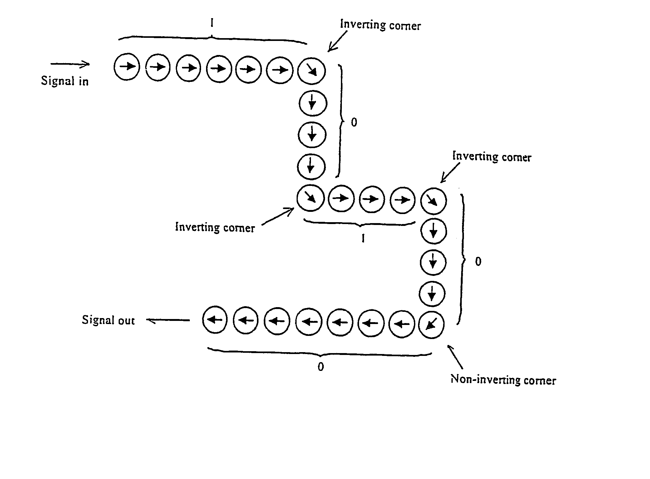
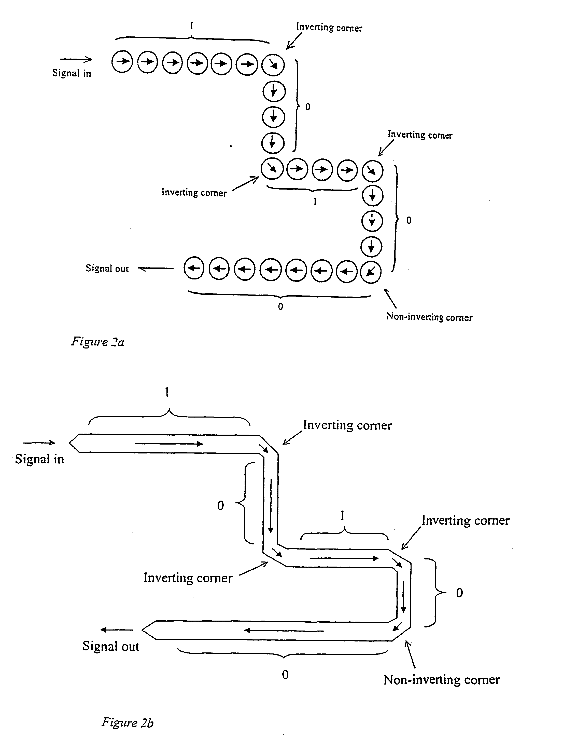
To produce effective interconnects and gates, deviation from strict linearity will be necessary through the provision of nodes, junctions and direction changes in the conduit, which will tend to produce less effective coupling along the track or between adjacent nanodots as the case may be and increase the energy required to propagate a soliton.
Such discontinuities would be expected to result in significant energy barriers to the propagation of a soliton across the discontinuity.
In extreme cases there might be a tendency for stray nucleation events to occur, and to therefore produce magnetic breakdown in the logic device.
The use of a transition zone reduces the maximum energy mismatch at any given point in the approach to the discontinuity and thus reduces the propagation energy, maintaining a large effective gap between propagation and nucleation energy and minimising the likelihood of undesired nucleation events.

Method used


Image

  • Magnetic logic elements
  • Magnetic logic elements
  • Magnetic logic elements

Examples


Embodiment Construction

[0057] An example mode of operation is first described and is then used to develop example architectures for practical logic devices in accordance with the invention.

[0058] (i) Clocking

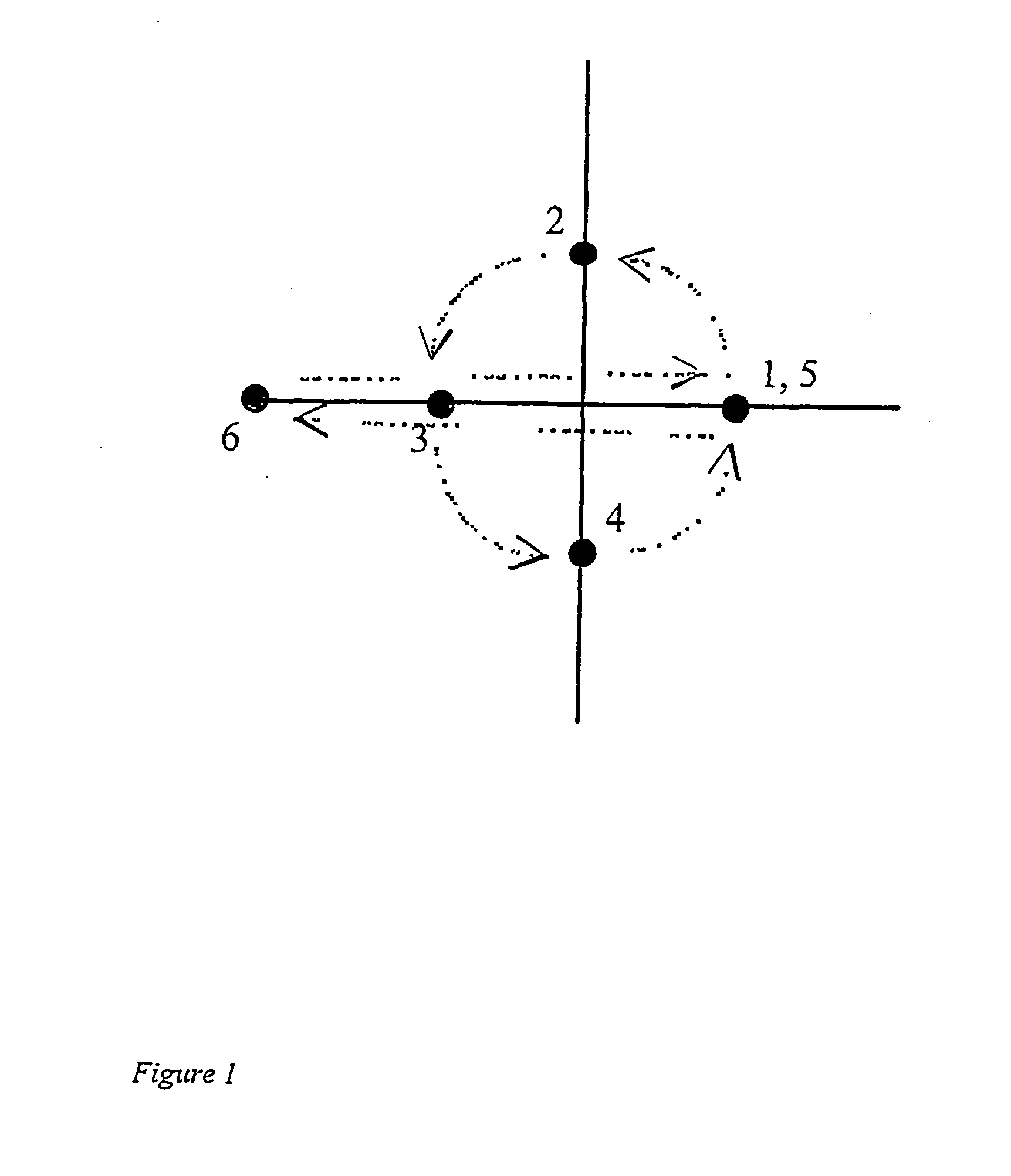
[0059] According to the example mode of operation used to develop the example architectures hereinafter, a magnetic field is applied to the logic device which acts both as power supply and as clock. The clock has six different phases per period; FIG. 1 shows these schematically.

[0060] In FIG. 1 is illustrated a polar plot showing the locus of the magnetic clock field vector during one clock period. The field vector begins the period pointing to the right at phase 1. It then proceeds to rotate anti-clockwise through phases 2, 3, and 4 and then back to where it started at phase 5. These 5 phases all have constant magnitude. In phase 6 it jumps to a large left-pointing value before returning to phase 1.

[0061] The phases can be applied either as a continuous rotation of the magnetic field or as discrete j...


PUM


Abstract

A magnetic logic element for a logic device is described formed by at least one conduit capable of sustaining and propagating a magnetic soliton, the conduit being adapted by the provision of nodes and / or directional changes giving rise to discontinuities in soliton propagation energy as a result of which logical functions may be processed. Magnetic logic devices such as interconnects and gates, and magnetic logic circuits incorporating such devices and suitable operational fields, are also described.

Description

[0001] This application claims priority under 35 U.S.C .sctn..sctn. 119, 120 to Great Britain Application No. 0028092.5, filed Nov. 17, 2000 and PCT Application No. GB01 / 05072, filed Nov. 19, 2001.[0002] 1. Field of Invention[0003] The invention relates to the provision of logic elements for logic devices and logic circuitry using the properties of magnetic quantum cellular automata, and in particular to an architecture for the design of such logic elements and devices and for the design and operation of logic circuitry using such elements.[0004] 2. Description of Related Art[0005] The number of transistors on a microchip has doubled every 18 months for the past 30 years, a phenomenon known as `Moore's Law`. Fundamental physical phenomena associated with small particles make this exponential growth increasingly difficult to sustain. One option already being considered by the semiconductor memory industry is to incorporate nanometre sized magnetic particles (`nanomagnets`) into micro...

Claims


Application Information

Patent Timeline
Patent Type & Authority Applications(United States)
IPC IPC(8): G06N99/00B82B1/00G11C11/14G11C13/02G11C19/08H03K19/02H03K19/18
CPCB82Y10/00G06N99/002H03K19/18G11C19/0816G11C2213/81G11C11/14G06N10/00G06N99/00
Inventor COWBURN, RUSSELL PAUL
Owner HORST SIEDLE GMBH & CO KG
Learn More