
Mirror device for a vehicle

Active Publication Date: 2004-02-05
KK TOKAI RIKA DENKI SEISAKUSHO
View PDF8 Cites 3 Cited by
  • Summary
  • Abstract
  • Description
  • Claims
  • Application Information

AI Technical Summary

Benefits of technology

[0026] The engage-member provided in one of the holding member and the supporting member has elasticity in the first direction and also has rigidity in the second direction. Further, the engagement claw provided in the other of the holding member and the supporting member has the protruding portion. The protruding portion elastically deforms the engage-member in the first direction in order to pass over (ride over) the engage-member. After the protruding portion passes over, elastic deformation of the engage-member by the protruding portion is released and the protruding portion of the engagement claw is engaged with the engage-member in the second direction, thereby resulting in the holding member being assembled to the supporting member.
[0027] In this manner, the engagement claw is engaged with the engage-member after elastic deformation of the engage-member by the protruding portion in the first direction, thereby allowing the holding member to be assembled to the supporting member. Accordingly, the use of a conventional jig or tool can be eliminated, and assembling equipment for assembling the holding member to the supporting member can be made unnecessary. Further, elastic deformation of the engage-member by the protruding portion of the engagement claw can be achieved by a low power (low load). Therefore, an operation of assembling the holding member to the supporting member can be facilitated.
[0028] Moreover, since the engage-member has rigidity in the second direction as is described above, the engagement claw is engaged with the engage-member at the protruding portion of the engagement claw in the second direction, thereby allowing the holding member to be assembled to the supporting member by a large assembling force. Accordingly, only with a structure in which the engage-member has elasticity in the first direction and has rigidity in the second direction, the holding member can be assembled to the supporting member by a large assembling force. Further, high-precision management of the strength of the engage-member and / or high-precision formation of the shape of the engage-member is not required. As a result, production of an assembling structure for assembling the holding member to the supporting member can be facilitated.
[0029] In the mirror device for a vehicle according to the second and seventh aspects of the present invention, when the holding member is assembled to the supporting member, the engagement protrusion provided in the other of the holding member and the supporting member is engaged with the engagement hole provided in one of the holding member and the supporting member. Accordingly, the engagement claw is guided to the engage-member and can reliably be engaged therewith, and the holding member can reliably be assembled to the supporting member. Further, the holding member can be positioned in the supporting member, and looseness of the holding member with respect to the supporting member in a direction perpendicular to the engagement hole and the engagement protrusion can be prevented.
[0031] In the mirror device for a vehicle according to the third aspect of the present invention, when the holding member is assembled to the supporting member, the holding member is made to abut on the supporting member in such a manner the holding member is pressed by the supporting member toward the supporting member. For example, the engage-member presses the protruding portion of the engagement claw. As a result, looseness of the holding member with respect to the supporting member, toward the supporting member side and the opposite side, can be prevented.
[0032] Further, in a case in which the supporting member presses the holding member toward the supporting member by means of members other than the engage-member and the protruding portion of the engagement claw, even if the engage-member and the protruding portion are not abutted on each other, looseness of the holding member toward supporting member side and opposite side can be prevented. Accordingly, a space can be formed between the protruding portion and the engage-member, and the protruding portion can reliably pass over the engage-member. Further, it is not necessary that the engage-member and the engagement claw (including the protruding portion) may be formed into high-accurate sizes, and the engage-member and the engagement claw can be formed in a simple manner.

Problems solved by technology

Accordingly, there arises a problem in which assembling equipment used for mounting (assembling) the mirror surface angle adjustment mechanism to the door mirror visor is needed.
Accordingly, there arises a problem in that it is hard to manufacture a structure for mounting the mirror surface angle adjustment mechanism to the door mirror visor.

Method used


Image

  • Mirror device for a vehicle
  • Mirror device for a vehicle
  • Mirror device for a vehicle

Examples


first embodiment

[0039] [First Embodiment]

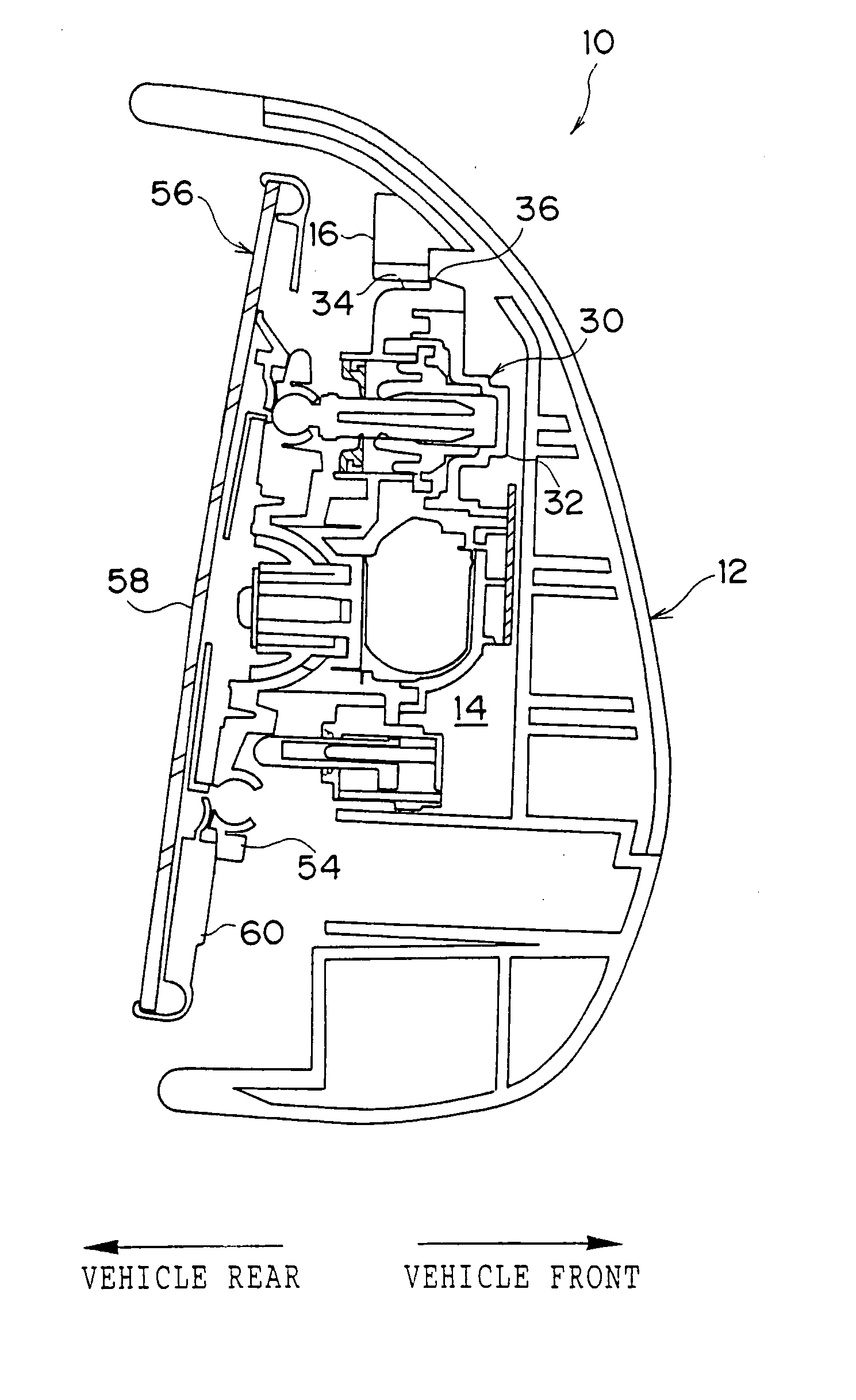
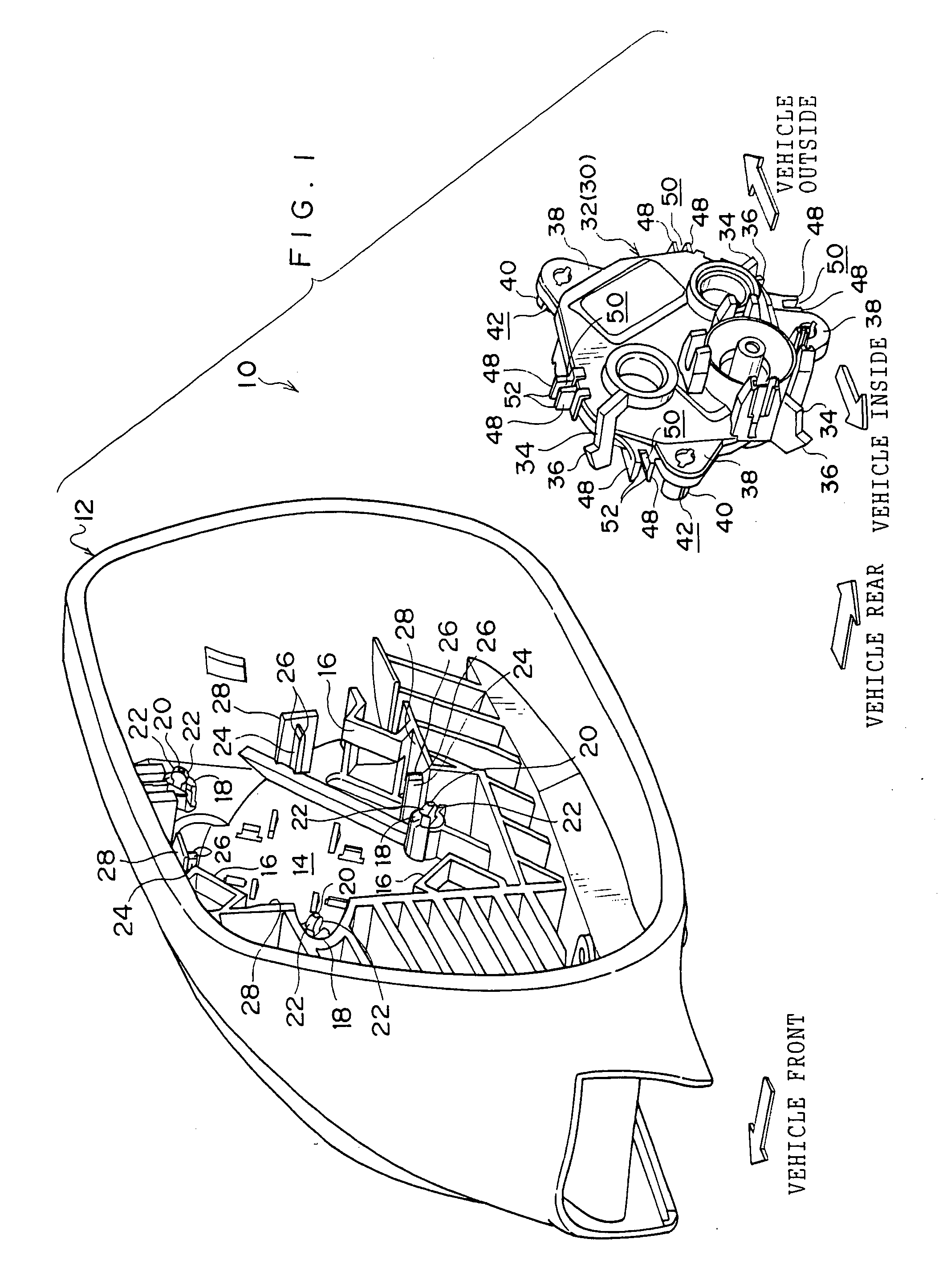
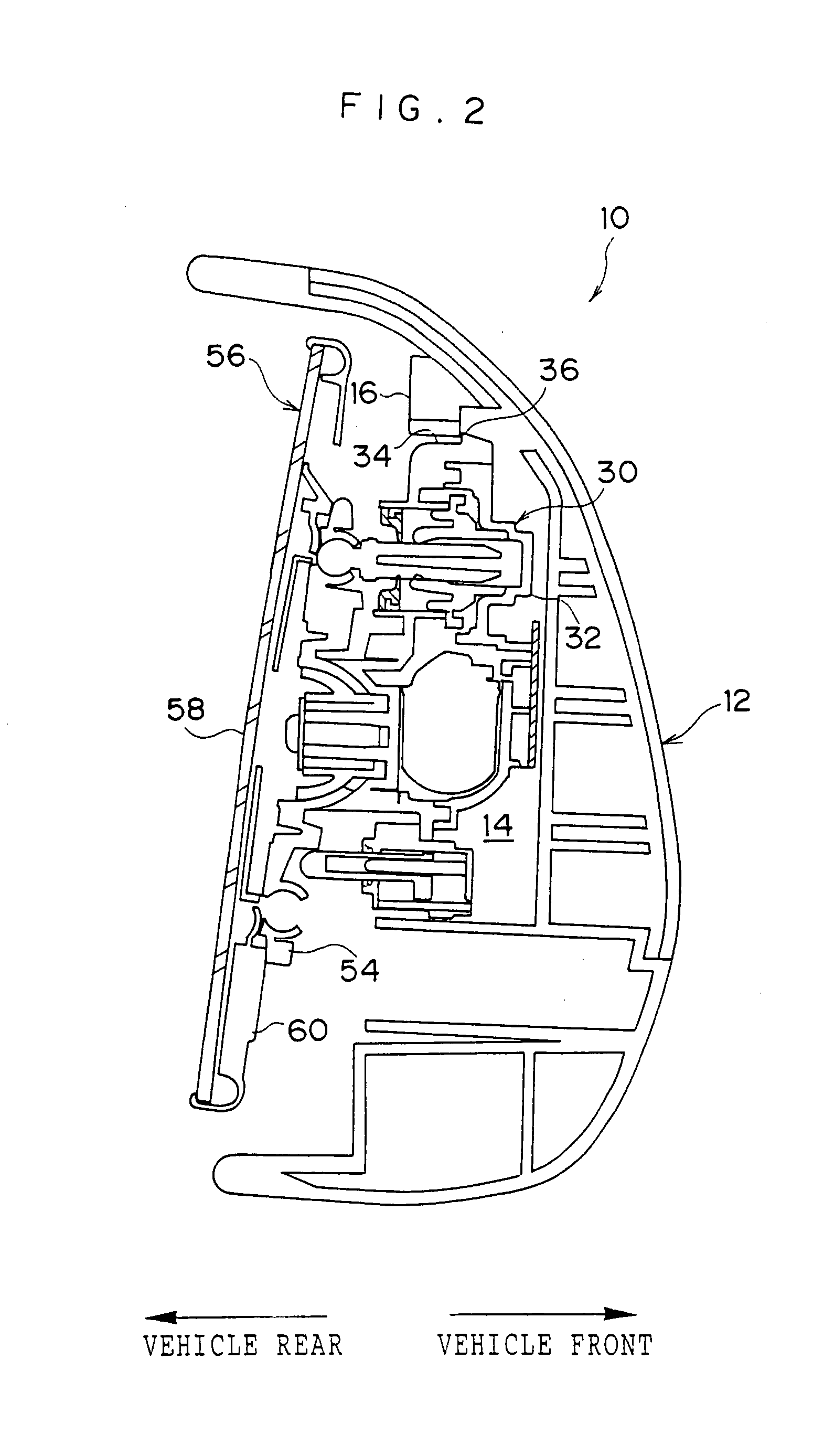
[0040] An exploded perspective view of a principal portion of a door mirror device 10 for a vehicle according to a first embodiment, to which a mirror device for a vehicle of the present invention is applied, is shown in FIG. 1. A cross-sectional view of the door mirror device 10 for a vehicle is shown in FIG. 2.

[0041] The door mirror device 10 for a vehicle according to the present embodiment is provided with a door mirror stay (not shown in the drawings), and the door mirror stay is fixed to a vehicle door (not shown in the drawings). A housing mechanism (not shown in the drawings) is supported by the door mirror stay, and a door mirror visor 12 serving as a supporting member is fixed to the housing mechanism. As a result, the door mirror visor 12 is connected to a vehicle body via the housing mechanism and the door mirror stay. Further, the door mirror visor 12 is formed in the shape of a box having an opening, the opening being formed at the vehicle rear...

second embodiment

[0068] [Second Embodiment]

[0069] FIGS. 6A and 6B each show a partially cut-away side view of a door mirror device 70 for a vehicle according to a second embodiment of the present invention to which the mirror device for a vehicle of the present invention is applied.

[0070] The door mirror device 70 for a vehicle according to the second embodiment is structured substantially in the same manner as in the door mirror device 10 for a vehicle according to the first embodiment except for the following structures.

[0071] The predetermined number of engage-members 16 are not provided in the outer periphery of the assembling portion 14 in the door mirror visor 12.

[0072] A flat plate-shaped insert protrusion 72 serving as an engagement claw and an engagement protrusion is provided, in place of the insert protrusion 20 of the above-described first embodiment, on a vehicle-rear-side surface 18a of each abut-pillar 18 in the door mirror visor 12. Each insert protrusion 72 has rigidity and protrude...


PUM


Abstract

In order to eliminate use of assembling equipment for assembling a holding member to a supporting member, a mirror device for a vehicle, having the holding member which holds a mirror and the supporting member which is connected to a vehicle body and assembled with the holding member, comprising an engage-member provided in one of the holding member or the supporting member, the engage-member having elasticity in a first direction and having rigidity in a second direction, and an engagement claw provided in the other of the holding member and the supporting member, the engagement claw having a protruding portion, wherein the holding member is assembled to the supporting member by the protruding portion of the engagement claw being engaged with the engage-member in the second direction due to that the protruding portion causes the engage-member to elastically deform in the first direction, and passes over the engage-member, is provided.

Description

[0001] This application claims priority under 35 USC 119 from Japanese Patent Application No. 2002-192886, the disclosure of which is incorporated by reference herein.[0002] 1. Field of the Invention[0003] The present invention relates to a mirror device for a vehicle, which is equipped with a mirror for visualizing rearward.[0004] 2. Description of the Related Art[0005] A door mirror device for a vehicle is provided with, for example, a door mirror stay. The door mirror stay is fixed to a vehicle door. The door mirror stay supports a door mirror visor and the door mirror visor is connected to a vehicle body via the door mirror stay.[0006] A mirror surface angle adjustment mechanism is assembled to the door mirror visor, and a mirror for visualizing rearward is assembled to the mirror surface angle adjustment mechanism. As a result, the mirror is held by the mirror surface angle adjustment mechanism and is supported by the door mirror visor via the mirror surface angle adjustment me...

Claims


Application Information

Patent Timeline
IPC IPC(8): B60R1/06B60R1/072F16B5/10F16B21/07
CPCB60R1/072B60R1/06
Inventor ISHIGAMI, NARUMI
Owner KK TOKAI RIKA DENKI SEISAKUSHO
Learn More