
Process for mapping multiple-bounce ghosting artifacts from radar imaging data

a radar imaging and artifact technology, applied in the field of radar image formation, can solve the problems of insufficient prior art process, complex process, and difficult time, and achieve the effect of extending the field of use and facilitating the identification of features of interes

Inactive Publication Date: 2004-02-05
LEIDOS
View PDF13 Cites 9 Cited by
  • Summary
  • Abstract
  • Description
  • Claims
  • Application Information

AI Technical Summary

Benefits of technology

The patent text describes a problem in reflection data processing where the impinging wave may reflect off of multiple parts of an object before returning to the receiver. This results in multiple-bounce scattering events that can cause difficulties in determining the physical distribution of scattering centers. Current processing schemes also place the multiple-bounce echoes at incorrect locations due to fundamental assumptions. The technical effect of this patent is to develop a modified image formation process that can account for multiple-bounce scattering events and accurately determine the physical distribution of scattering centers.

Problems solved by technology

A particular imaging scenario wherein the prior art process is insufficient includes determining the physical distribution of the scattering centers for cases in which multiple-bounce echoes occur.
For example, prior art processes would have a difficult time determining from three (3) received echoes that instead of three scattering centers for an object-of-interest, the image actually contained two targets, wherein the third echo was between the two scattering centers as opposed to a third scattering center.
The problem is exacerbated in a case where there are many scattering centers within the image, with the possibility for multiple bounces between the scattering centers.
Further, in the case of SAR imaging, the process becomes even more complicated by the fact that the object (or region)-of-interest radar information is only gathered over a very small aspect angle range, for example, up to approximately 15 degrees.

Method used


Image

  • Process for mapping multiple-bounce ghosting artifacts from radar imaging data
  • Process for mapping multiple-bounce ghosting artifacts from radar imaging data
  • Process for mapping multiple-bounce ghosting artifacts from radar imaging data

Examples


Embodiment Construction

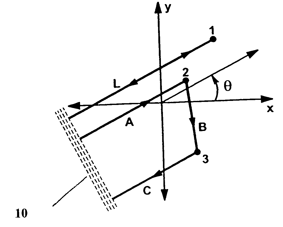
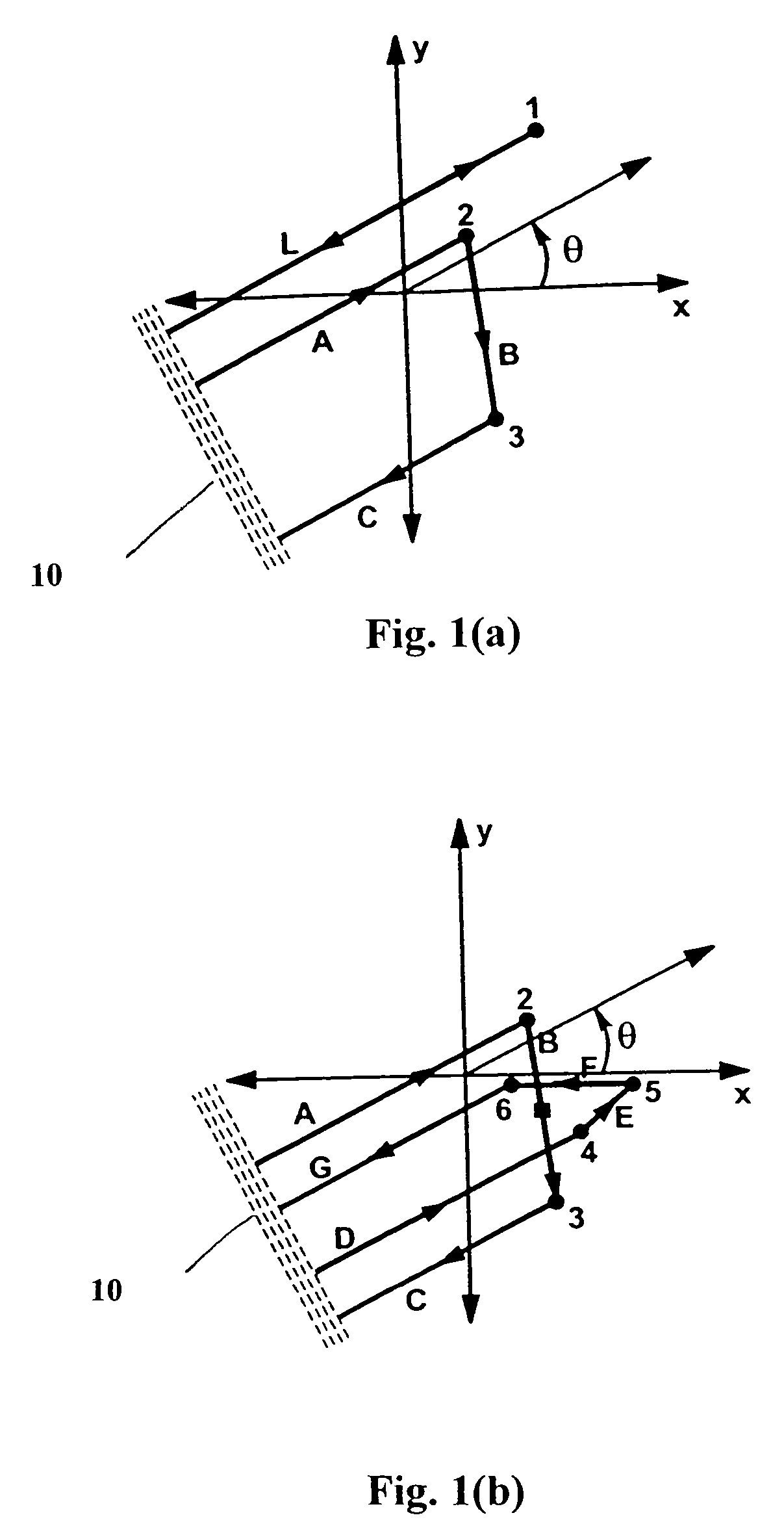
[0025] In a preferred embodiment of the present invention, the imaging process assumes the condition that a scattered waveform has the same characteristics as the incident waveform. In the context of SAR imaging, the measured range to target (i.e., assumed object-of-interest) of a given multiple bounce (MB) scattering event at some aperture angle is identical to that of an equivalent single bounce (SB) scattering event. FIG. 1a presents an example of such equivalent scattering events. In this example, the transmitter is co-located with the receiver (both shown as 10) at a large distance from the region-of-interest, so that the effects of a curved wave front can be neglected. One skilled in the art recognizes that the process described herein may be adjusted for non co-located transmitter and receiver configurations, as well as for distances from the region of interest which result in curved wavefronts. FIG. 1a shows that waveform traverses a total distance of 2L in propagating from ...


PUM


Abstract

Described herein are frequency-domain back-projection processes for forming spotlight synthetic aperture radar ("SAR") images that are not corrupted by the effects of multiple-bounce ghosting artifacts. These processes give an approximately exact reconstruction of the multiple bounce reflectivity function (MBRF) f(x,y,gamma). Specifically, the evaluation off f(x,y,gamma) in the gamma=0 plane gives an approximately exact reconstruction of the true object scattering centers which is uncorrupted by multiple-bounce contributions to the phase history data G(xi,theta). In addition, the non-zero dependence of f(x,y,gamma) upon the MB coordinate gamma can be used to facilitate the identification of features-interest within the imaged region.

Description

[0001] This application claims priority to and incorporates by reference in its entirety, U.S. Provisional Patent Application No. 60 / 345,639, entitled "SPOTLIGHT SAR IMAGE FORMATION WITHOUT MULTIPLE-BOUNCE GHOSTING ARTIFACTS" filed Jan. 8, 2002.[0002] 1. Field of the Invention[0003] Generally, the invention involves a process for forming radar images. More specifically, the invention involves a process for mapping multiple bounce ghosts (MBGs) and for forming radar images without the deleterious effects of MBGs.[0004] 2. Description of the Related Art[0005] Radar, at its most basic application, is used to measure the range to a target. With knowledge of the speed of propagation of the wave, i.e., electromagnetic wave, that is transmitted toward the target, it is possible to resolve in a first dimension, the distance to the target, based on the received reflected wave or echo. In order to use radar as an imaging tool, it is necessary to collect information about the cross-range of th...

Claims


Application Information

Patent Timeline
Patent Type & Authority Applications(United States)
IPC IPC(8): G01S13/90
CPCG01S7/52077G01S13/9035G01S2013/9052G01S15/8977G01S15/8906G01S13/9017G01S13/9052
Inventor GARREN, DAVID ALAN
Owner LEIDOS
Learn More