
Optical disk apparatus

Inactive Publication Date: 2004-01-15
TEAC CORP
View PDF5 Cites 28 Cited by
  • Summary
  • Abstract
  • Description
  • Claims
  • Application Information

AI Technical Summary

Problems solved by technology

However, in the optimization steps, there may arise a case where jitter of the overwritten test data varies according to the magnitude of an RF amplitude of the test data that have already been recorded even when the same write power is employed during overwriting operation.
For this reason, when the test data that have already been recorded have a large RF amplitude, jitter of the overwritten test data becomes deteriorated.
Thus, the method--in which test data are overwritten by merely changing the write power in a plurality of levels and optimum write power is selected on the basis of the jitter of the overwritten test data--involves a problem of optimum write power not always being true optimum write power that can effect overwriting regardless of an RF amplitude of the data that have already been recorded.
Such high write power deteriorates durability, such as the number of rewriting operations.
However, in view of durability, the method is not the best setting method.
When a comparatively large difference exists between the first reproduced signal quality and the second reproduced signal quality, overwriting operation is susceptible to the influence of the RF amplitude of test data that have already been recorded.

Method used


Image

  • Optical disk apparatus
  • Optical disk apparatus
  • Optical disk apparatus

Examples


Embodiment Construction

[0024] The present invention will be described in detail hereinbelow by reference to the drawings.

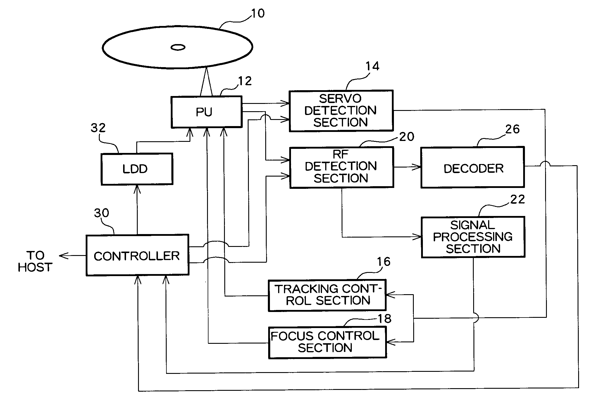
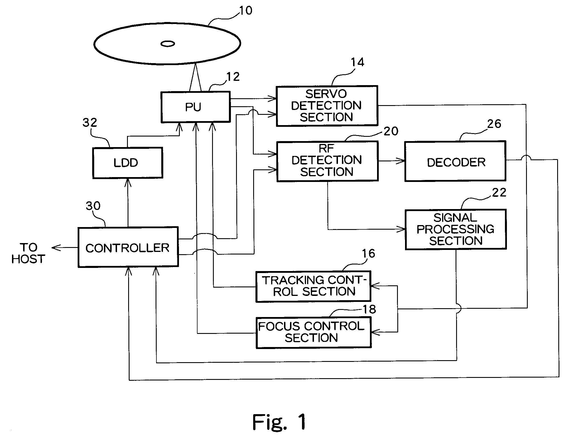
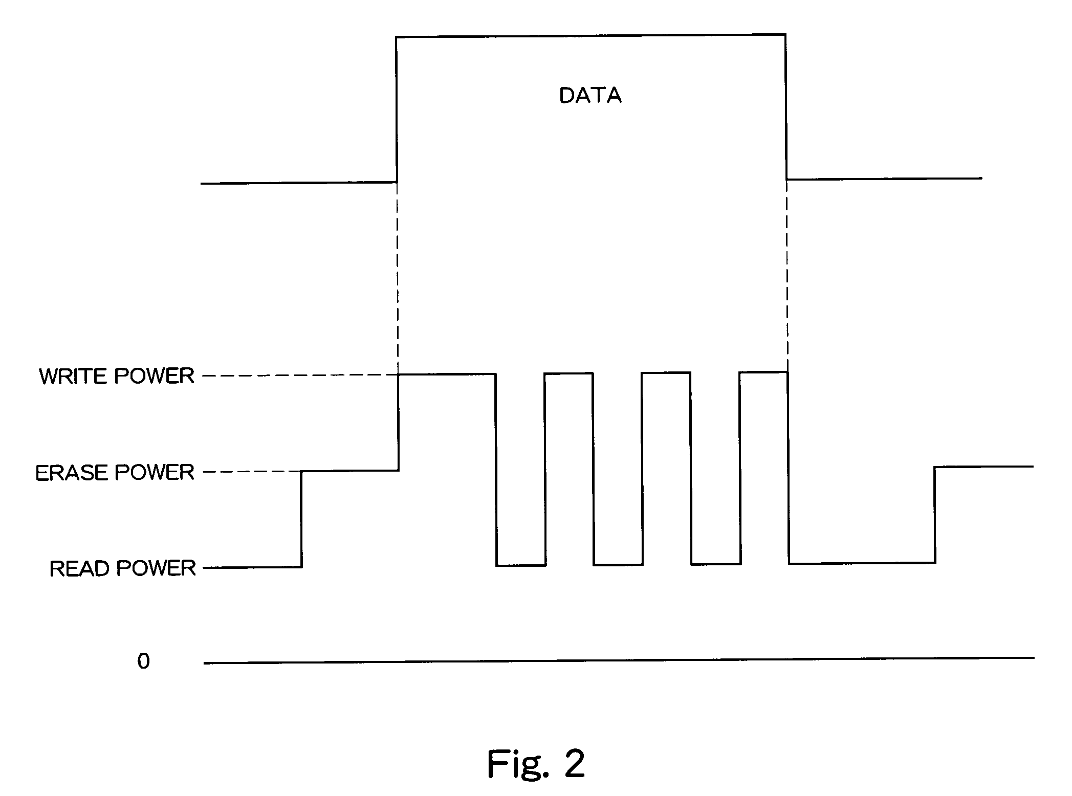
[0025] FIG. 1 is a block diagram showing the overall configuration of an optical disk apparatus according to an embodiment. An optical pickup (PU) 12 is disposed so as to oppose an optical disk 10 and is configured so as to include a laser diode (LD) for radiating a laser beam onto the surface of the optical disk 10 and a photo detector (PD). The LD is activated by a laser diode drive circuit (LDD) 32. When data are reproduced from the optical disk 10, a laser beam of read power is output from the LD. When data are recorded on the optical disk 10, a laser beam having read power on which erase power and write power are superimposed is output from the LD. A rewritable optical disk, such as a DVD-RW, DVD+RW, DVD-RAM or the like, is used as the optical disk 10. The PD of the optical pickup 12 includes a PD for receiving a main beam in the same manner as a photo detector of known configurati...


PUM


Abstract

An optical disk apparatus for recording data on an optical disk. Prior to recording data on the optical disk, a controller records test data in a test area of the optical disk, thereby optimizing write power. After having recorded the test data, the controller computes a difference between jitter or an error rate obtained when test data are overwritten at write power higher than that used for recording test data and jitter or an error rate obtained when test data are overwritten at write power lower than that used for recording the test data. A jitter or error rate difference is detected while write power is changed. Write power at which the jitter or error rate difference is smaller than or equal to a predetermined threshold value is selected as optimum write power, and data are recorded in a data area.

Description

[0001] 1. Field of the Invention[0002] The present invention relates to an optical disk apparatus, and more particularly, to optimization of write power.[0003] 2. Description of the Related Art[0004] An optical disk apparatus for recording data on a rewritable optical disk, such as a CD-RW, DVD-RW, or DVD-RAM, has already been developed. The optical disk apparatus records data after having optimized write power. The followings are steps for optimizing write power.[0005] (1) The optical disk apparatus records test data in a predetermined area [test area: PCA (Power Calibration Area)] of an optical disk.[0006] (2) The optical disk apparatus overwrites test data at the same location by changing write power in a plurality of levels.[0007] (3) The optical disk apparatus reproduces the test data after overwriting, to thereby measure jitter for each level of write power employed.[0008] (4) The optical disk apparatus sets the write power, at which jitter becomes minimum, as optimum write po...

Claims


Application Information

Patent Timeline
IPC IPC(8): G11B7/0045G11B7/006G11B7/125G11B7/1267
CPCG11B7/1267G11B7/0062
Inventor TOKITA, YUHITAKEDA, NAOTO
Owner TEAC CORP
Learn More