
Surface light source device of side light type, liquid crystal display and guide plate

a technology of liquid crystal display and surface light source, which is applied in the direction of optical light guide, identification means, instruments, etc., can solve the problems of reducing affecting the appearance quality, and affecting the quality of illumination output, so as to prevent the appearance of fine bright-dark unevenness

Inactive Publication Date: 2003-12-18
ENPLAS CORP +1
View PDF2 Cites 16 Cited by
  • Summary
  • Abstract
  • Description
  • Claims
  • Application Information

AI Technical Summary

Benefits of technology

[0020] The present invention is proposed under the above-described background. An object of the present invention is to provide a surface light source device of side light type improved so that fine bright-dark unevenness is prevented from being caused by difference in characteristics between regions occupied by light scattering elements distributed on an emission face of a guide plate and the other region among the light scattering elements and to provide a liquid crystal display to which the improved surface light source device is applied as well as a guide plate which brings the improvement to the devices.
[0021] Another object of the present invention is to provide a surface light source device of side light type improved so that a guide plate disposed directly on an emission face of a guide plate is free from sticking to the emission face and to provide a liquid crystal display to which this improved surface light source device is applied as well as a guide plate which brings this improvement to the devices.
[0022] The present invention can be applied to a surface light source device of side light type comprising a guide plate having a minor face to provide an incidence end face and two major faces to provide an emission face and a back face as well as a primary light source arranged so that the guide plate is supplied with primary light through the incidence end face and can be applied also to a liquid crystal display employing the surface light source device for backlighting of a liquid crystal display panel. And the present invention improves a guide plate employed in the devices.
[0024] Such a rough area formed among the light scattering elements enables a prism sheet to reduce tendency of sticking thereto. Accordingly, the prism sheet, if directly disposed on the emission face, is prevented from sticking.

Problems solved by technology

Such prior art suffers from problem as follows.
As a result, surface light source devices of side light type employing such guide plates with bright-dark unevenness suffer from reduction in quality (smoothness) of illumination output.
And needless to say, LCDs in which such surface light source devices of side light type for backlighting are incorporated suffer from reduction in display quality.
However, the above proposed technique suffers from a unsolved problem.
Such sticking produces bright-dark pattern on an output face (i. e. an outer face of the most outside additional member), as shown in FIG. 9, thereby reducing quality of illumination output.
In particular, when any foreign body such as trash is interposed between a guide plate and a prism sheet, troublesome operations are required for removing the foreign body.

Method used


Image

  • Surface light source device of side light type, liquid crystal display and guide plate
  • Surface light source device of side light type, liquid crystal display and guide plate
  • Surface light source device of side light type, liquid crystal display and guide plate

Examples


Embodiment Construction

(1) Embodiment

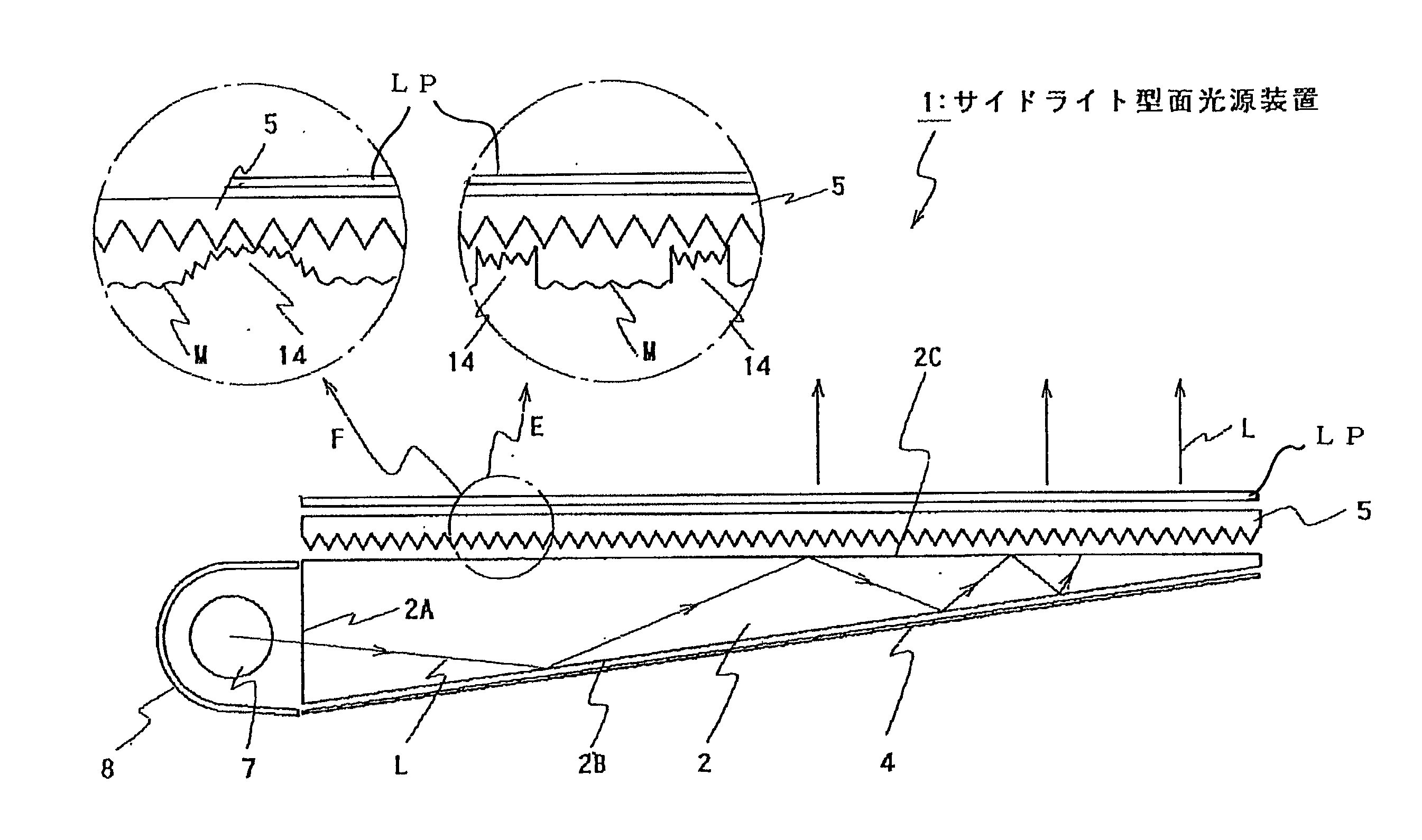
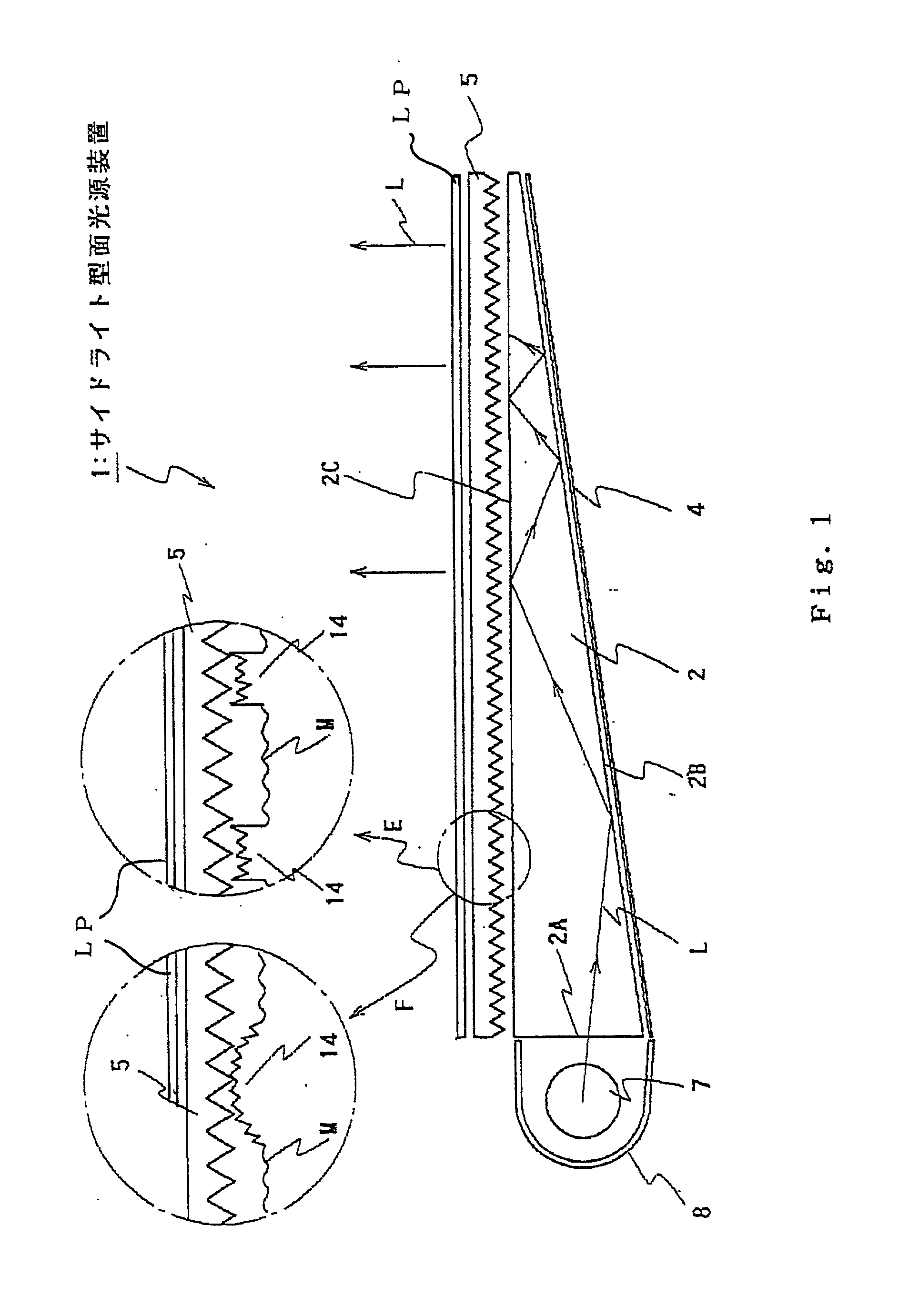
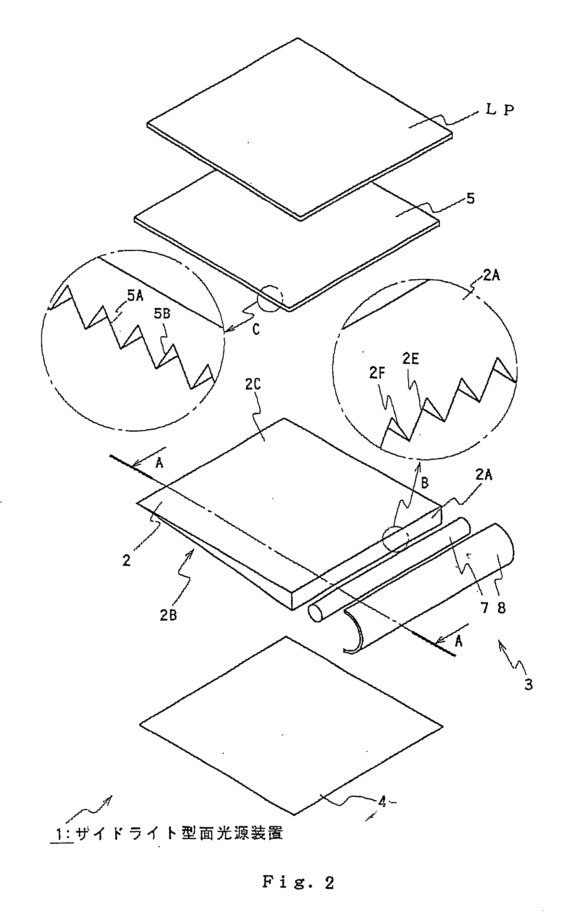
[0036] Referring to FIGS. 1 and 2, a surface light source device of side light type 1 comprises a guide plate 2, a primary light source 3, a reflection sheet 4 and a flexible prism sheet 5 as a light control member. The reflection sheet 4, the scattering guide plate 2 and the prism sheet 5 are laminatedly arranged. The guide plate 2 has a wedge-like cross section with a thicker end potion having a minor face to provide an incidence end face 2A beside which the primary light source is disposed.

[0037] The primary light source 3 is, for example, provided by a cold cathode lamp (fluorescent lamp) 7 backed by a reflector 8. The fluorescent lamp) 7 emits illumination light (primary light) which is supplied to the incidence end face 2A of the scattering guide plate 2 through an opening of the reflector 8. The reflector is a sheet-like member with regular or irregular reflectivity.

[0038] The reflection sheet 4 is, for example, a sheet-like member with regular reflectivity prov...


PUM


Abstract

A LCD panel is illuminated from its back side by a surface light source device of side light type comprising a guide plate, a primary light source (fluorescent lamp and reflector), a reflection sheet and a prism sheet as a light control member. Light scattering pattern and rough area M are foxed on an emission face of the guide plate. The light scattering pattern consists of a great number of fine light scattering elements. The rough area M is formed among the light scattering elements and has scattering power which is weaker than that of the light scattering elements. The dot-like light scattering elements are distributed according to a certain pattern. This pattern is designed depending on necessity of promotion of emitting. Emitting is promoted in not only portions where the light scattering elements are formed but also in the area M among them. Accordingly, fine periodic bright-dark unevenness and glaring are hard to appear. And even when an additional member such as prism sheet is disposed directly on the emission face, the additional member is prevented from sticking to the emission face. The rough area M has roughness practically falling within a range from 0. 02 to 0.25 mum.

Description

[0001] 1. Field of Invention[0002] The present invention relates to a surface light source device of side light type, a liquid crystal display (LCD) and a guide plate used for the devices, in particular, to the guide plate having an incidence end face, an emission face and back face provided by a minor face and two major faces, respectively, as well as to the devices with improved illumination characteristics or display characteristics by employing the improved guide plate.[0003] 2. Related Art[0004] It is well known to employ a surface light source device of side light type for illuminating a LCD panel of a LCD. In general, the surface light source device of side light type comprises a guide plate and a primary light source such as rod-like light source, the primary light source being disposed along an incidence end face of the guide plate. Such arrangement has an advantage that the arrangement can be applied to LCDs without increase in overall size.[0005] Primary light emitted fro...

Claims


Application Information

Patent Timeline
IPC IPC(8): G02B6/00F21V8/00G02B5/02G02F1/1335G02F1/13357G09F9/00
CPCG02B6/0053G02B6/0043G02F1/1335
Inventor YAMAZAKI, HIROSHIOHKAWA, SHINGO
Owner ENPLAS CORP
Learn More