
Temporary wireless sensor network system

a wireless sensor and network system technology, applied in the field of temporary wireless sensor network system, can solve the problems of not enough data to identify the root, inability to justify the hardwiring of a new sensing location, or a new sensor type, and inability to prove the valu

Inactive Publication Date: 2003-10-30
CHEVROU USA INC
View PDF36 Cites 76 Cited by
  • Summary
  • Abstract
  • Description
  • Claims
  • Application Information

AI Technical Summary

Benefits of technology

0024] In other embodiments the invention include other systems configured and adapted to perform the steps listed in the above-described methods, and computer readable media containing computer readable instructions configured and adapted to perform or assist in one or more of the steps listed in the above-described methods.
0025] These and other features and advantages of the present invention will be made more apparent through a consideration of the following detailed description of a preferred embodiment of the invention. In the course of this description, frequent reference will be made to the attached drawings.

Problems solved by technology

There are two general sensor related issues commonly found in process plants.
First, process plants are generally instrumented for normal operation and not for detailed trouble-shooting.
When everything is working fine, there is often too much data and it is discarded but when the process is not working properly then often there is not enough data to identify the root cause of the problem.
Second, justifying the hardwiring of a new sensing location, or new sensor type, is often not possible unless you can a priori prove its value, but you can't prove the value until you have the data.
However, it would be unduly expensive to permanently install such additional sensors to all process units or streams without regard to whether the units are experiencing problems.
The value of this additional data is not clear under normal operations and, in practice, this extra data can be an annoyance.
Justification of New Sensors and Sensing Locations: Testing a new type of sensor or adding an existing sensor type to a new sensing location can have a considerable expense and delay associated with it.
Determining the business value of a new sensor type or sensor point is often difficult without already having the data collected from the new sensor.

Method used


Image

  • Temporary wireless sensor network system
  • Temporary wireless sensor network system
  • Temporary wireless sensor network system

Examples


Embodiment Construction

[0031] A. Introduction

[0032] The following discussion and figures include a general description of a suitable computing environment in which the invention may be implemented. While the invention will be described in the general context of an application program that runs on an operating system in conjunction with a personal computer, those skilled in the art will recognize that the invention also may be implemented in combination with other program modules. Generally, program modules include routines, programs, components, data structures, etc. that perform particular tasks or implement particular abstract data types. Moreover, those skilled in the art will appreciate that the invention may be practiced with other computer system configurations, including hand-held devices, multiprocessor systems, microprocessor-based or programmable consumer electronics, minicomputers, mainframe computers, and the like.

[0033] The invention may also be practiced in distributed computing environments...


PUM


Abstract

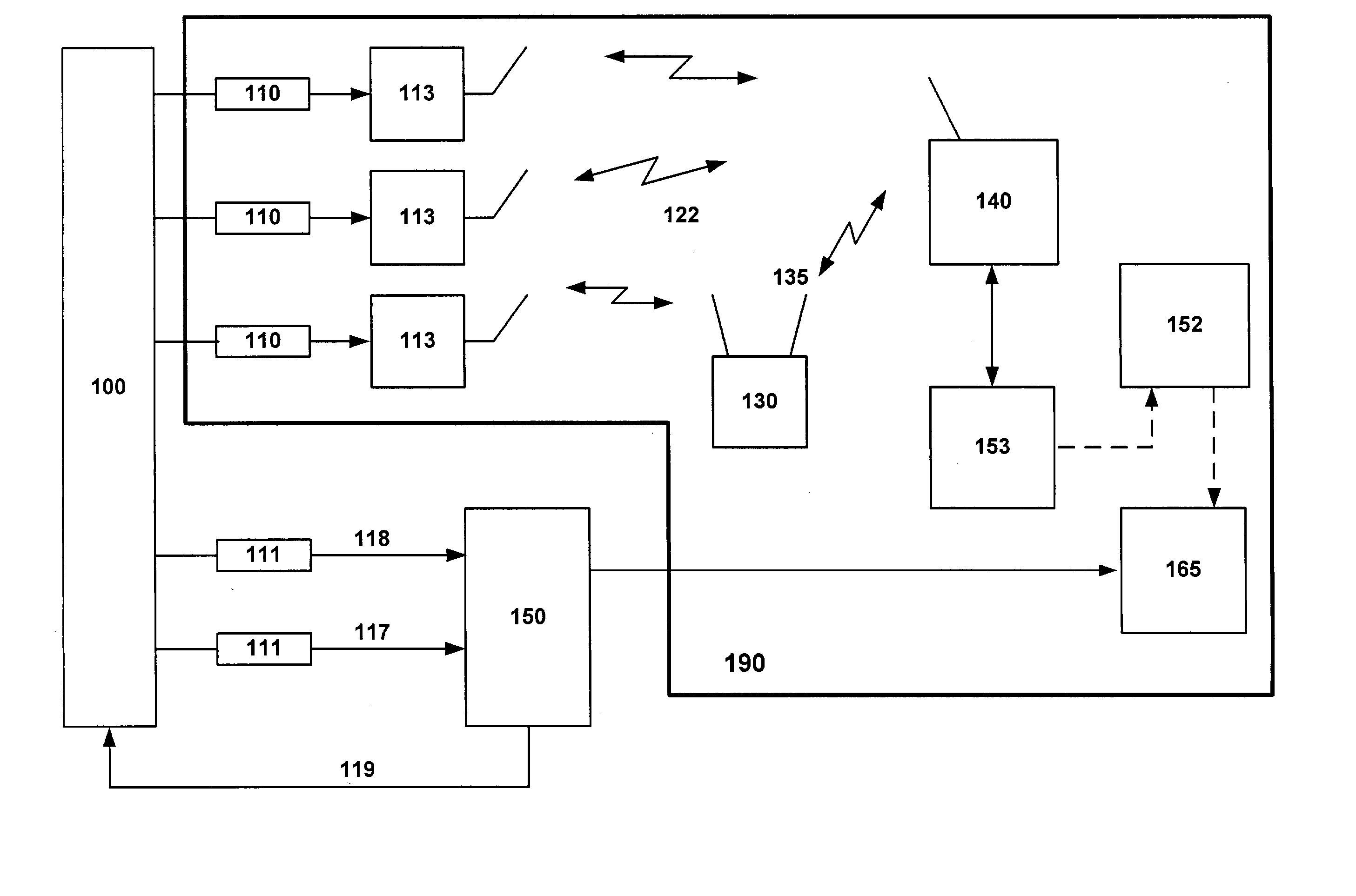
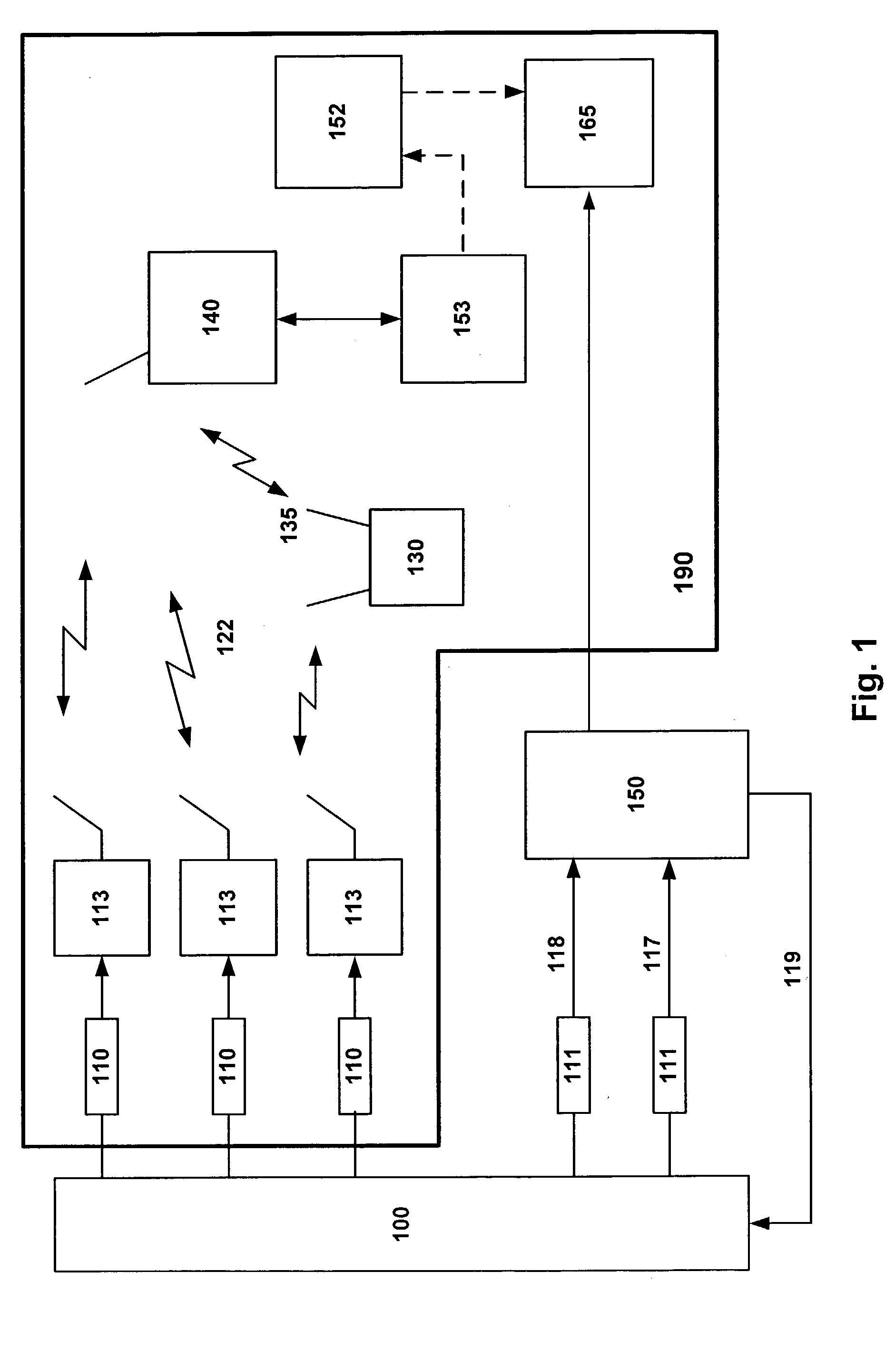
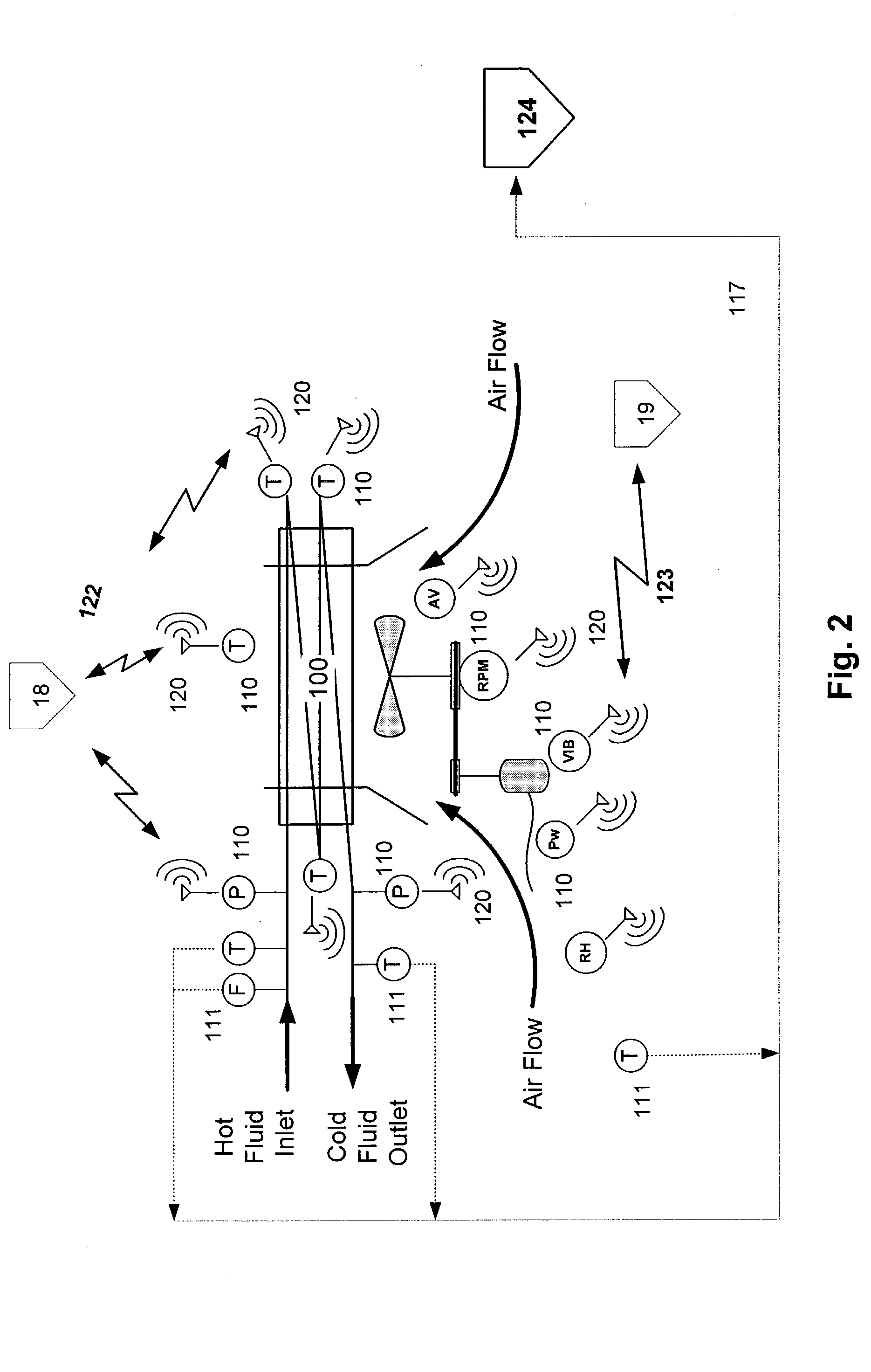
The invention is an integrated temporary wireless network system for controlling, collecting, processing, and responding to data generated by a plurality of sensors configured for measuring data associated with operation of, and the environment related to, commercial, industrial and manufacturing operations, processes and equipment located within a fixed geographic area; a plurality of Wireless-Nodes, one coupled to each sensor, configured and adapted for wirelessly transmitting the data, via a Repeater if necessary, to a Base-Station, configured for receiving the data and connected to a primary computer; a CPU coupled with the primary computer and; a memory operatively connected to the CPU, the memory containing a program adapted to be executed by the CPU and the CPU and memory cooperatively adapted to perform data flow control from the plurality of Wireless-Nodes, data storage, and diagnostic analysis of the transmitted sensor data.

Description

I. COPYRIGHT NOTICE AND AUTHORIZATION[0001] This patent document contains material which is subject to copyright protection.[0002] .COPYRGT. Copyright 2002-2003. Chevron U.S.A. Inc. All rights reserved.[0003] With respect to this material which is subject to copyright protection. The owner, Chevron U.S.A. Inc., has no objection to the facsimile reproduction by any one of the patent disclosure, as it appears in the Patent and Trademark Office patent files or records of any country, but otherwise reserves all rights whatsoever.II. FIELD OF THE INVENTION[0004] This invention relates to a system for monitoring, facilitation of trouble-shooting and problem diagnosis in commercial, industrial and manufacturing operations, processes and equipment, (collectively referenced hereinafter as "Industrial Process").III. BACKGROUND OF THE INVENTION[0005] Oil and gas processing, petroleum refining and chemical processing plants and many other processing, commercial and manufacturing industries curr...

Claims


Application Information

Patent Timeline
Patent Type & Authority Applications(United States)
IPC IPC(8): G05B23/02G06FG06F11/00G06F11/273G06F11/30G06F15/00G21C17/00G21D3/08
CPCG06F11/0736G06F11/0748Y02E30/40G21C17/00G21D3/08G06F11/2294Y02E30/30Y02E30/00
Inventor SCIAMANNA, STEVEN F.
Owner CHEVROU USA INC
Learn More