Method and apparatus for electromagnetic irradiation of liquid

Inactive Publication Date: 2003-07-31
EBARA ENG SERVICE
View PDF0 Cites 8 Cited by
  • Summary
  • Abstract
  • Description
  • Claims
  • Application Information

AI Technical Summary

Benefits of technology

[0005] The present invention has been made in view of the above drawbacks. It is an object of the present invention to provide an apparatus for and a method of applying an electromagnetic wave to treat a large amount of liquid stably without causing an electromagnetic wave source to be contaminated.
[0007] Since the overflow portion of the liquid retention tank and the inner wall surface of the cylinder are connected to each other by the curved surface of the inlet portion, a thin-film liquid layer can be formed stably on the inner wall surface of the cylinder even if the liquid flows in a large quantity. Consequently, the electromagnetic wave applying apparatus can increase the amount of the liquid treated thereby without contaminating the electromagnetic wave source.
[0029] The electromagnetic wave applying apparatus operates as follows: Ultraviolet rays which is a type of electromagnetic wave are applied from the ultraviolet lamp 11 disposed in the protective tube 12 to a thin film of the liquid W flowing down the inner wall surface of the cylinder 15. When the liquid layer flows over the upper overflow end of the inner wall surface of the cylinder 15 and down as a thin film along the inner wall surface of the cylinder 15, it is introduced through the inlet portion 17 in the form of a curved surface onto the inner wall surface of the cylinder 15. Therefore, the overflow from the liquid retention tank 16 is smoothly introduced as a thin film onto the inner wall surface of the cylinder 15, and smoothly flows down the inner wall surface of the cylinder 15. Therefore, there is produced a downwardly flowing liquid layer of uniform thickness without producing splashes and thickness irregularities. As the liquid swirls in the liquid retention tank 16 and forms a downwardly flowing layer from the inlet portion along the inner wall surface of the cylinder 15, the liquid is subject to centrifugal forces and has its surface stabilized and / or uniformized, so that the liquid overflow is supplied from all locations on the inlet portion at a constant rate to the inner wall surface of the cylinder 15 which is irradiated with ultraviolet rays. Since the liquid is given a swirling flow speed, even if the liquid contains suspended materials, they are prevented from being settled and / or accumulated in the liquid retention tank 16. Even when the liquid splashes, the liquid is scattered tangentially to the inner wall surface of the cylinder, rather than centrally toward the protective tube 12. Consequently, the liquid splashes are prevented from being applied to the protective tube 12, which is thus prevented from being contaminated. Furthermore, the thickness of the liquid layer is uniformized as the liquid is subject to centrifugal forces because of the swirling flow thereof. Due to the centrifugal forces acting on the liquid, the thin-film liquid on the inner wall surface of the cylinder 15 is retained thereon for a period of time longer than if there were no swirling flow thereon.
[0030] As shown in FIG. 4, the inner wall surface of a cylinder 15A which is irradiated with ultraviolet rays may be progressively smaller in diameter from the upper portion to the lower portion thereof. According to this modification, the liquid layer produced by the liquid that flows in from the inlet portion is prevented from being peeled off the inner wall surface of the cylinder 15A which is irradiated with ultraviolet rays. Therefore, even when the liquid is supplied in a large quantity, a thin-film liquid layer can stably be formed on the inner wall surface of the cylinder 15A.
[0034] The inner wall of the cylinder 15 which is irradiated with electromagnetic waves may be made of synthetic resins such as vinyl chloride, metals such as stainless steel, glass, and ceramics. If the liquid is mainly composed of water, then the surface of the inner wall may be combined with a hydrophilic material such as titanium dioxide, for example, for forming a thin film of liquid more stably. If ultraviolet rays are applied to titanium dioxide, then active oxygen is generated from dissolved oxygen, making organic substances more degradable. The inner wall surface of the cylinder 15 which is irradiated with electromagnetic waves may be of an ordinary cylindrical shape for producing a thin-film liquid layer. For stably forming a thin-film liquid layer from a large amount of liquid, however, the inner wall surface of the cylinder should preferably have a bell-mouthed upper portion and be progressively larger in diameter upwardly in a curved configuration.

Problems solved by technology

The process does not produce secondary waste materials and is capable of decomposing dioxins and so on in water.
However, the distance between the electromagnetic wave source and the liquid to be treated poses a problem.
If the distance between the electromagnetic wave source and the liquid to be treated is reduced and the electromagnetic wave source and the liquid to be treated are positioned closely to each other, then the radiated intensity of the electromagnetic wave can be achieved, but it is difficult to form a stable, high-speed thin film of liquid flowing down a vertical wall surface.
In case the amount of the liquid to be treated is large, however, the thickness of the film of liquid flowing down is increased, and when the speed of the flowing liquid is increased, the thin film of liquid becomes unstable, producing splashes which are scattered and contaminate the electromagnetic wave source.

Method used


Image

  • Method and apparatus for electromagnetic irradiation of liquid
  • Method and apparatus for electromagnetic irradiation of liquid
  • Method and apparatus for electromagnetic irradiation of liquid

Examples


example 2

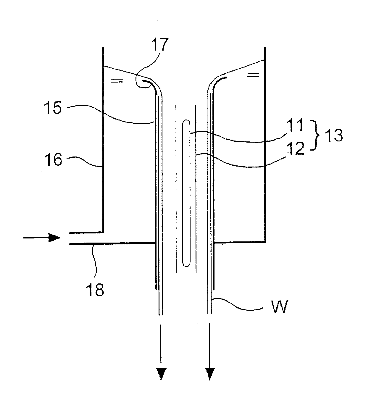
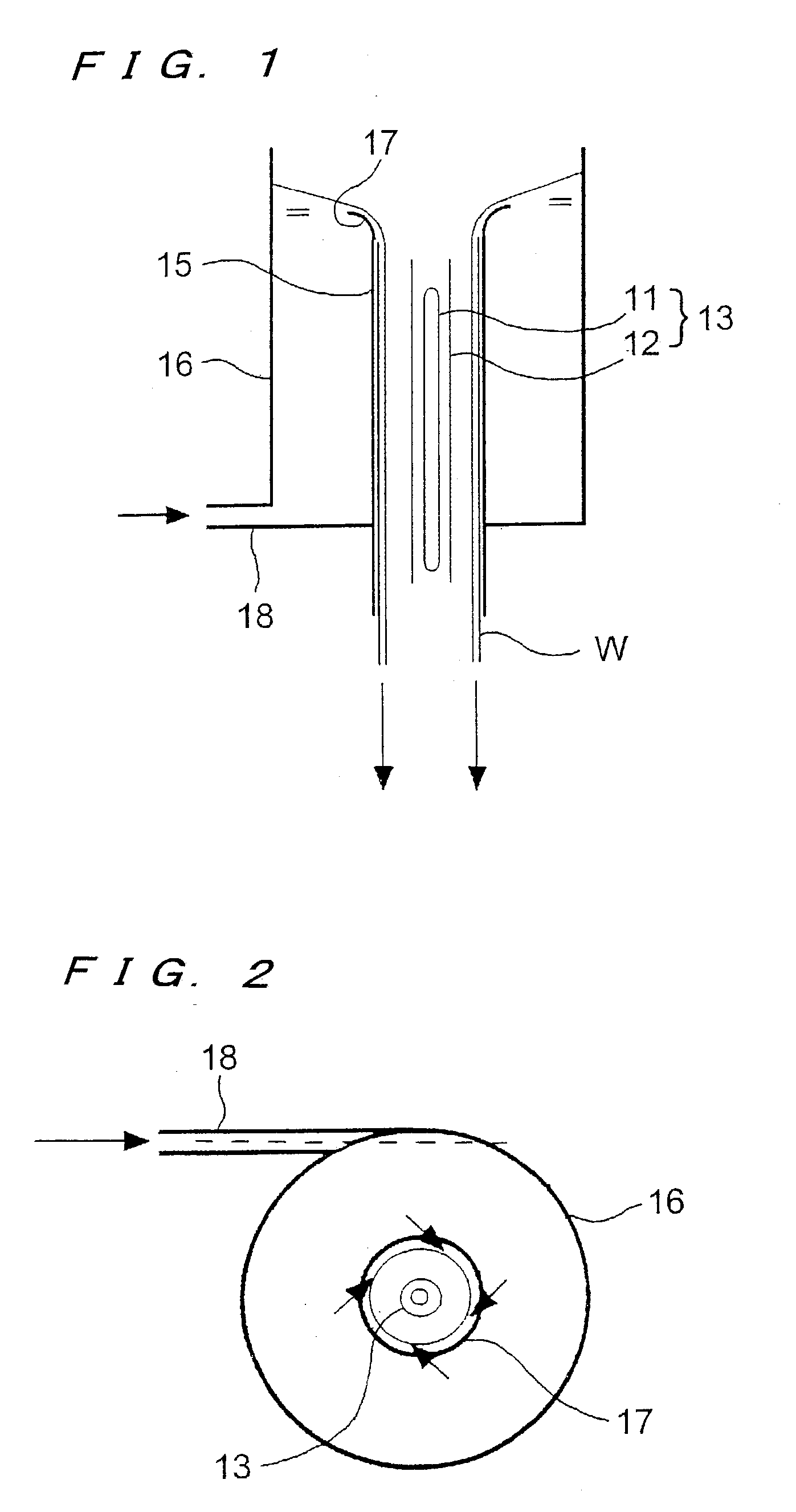
[0054] Using the apparatus shown in FIGS. 1 and 2, a liquid having a hexachlorobenzene concentration of 10 .mu.g / l, an iron concentration of 5 mg / l, and a manganese concentration of 5 mg / l was treated with ultraviolet rays under the same conditions as those of Example 1:

[0055] As a result, the applied intensity of the ultraviolet rays after elapse of 24 hours remained substantially unchanged, and hence was substantially constant throughout the 24 hours. The hexachlorobenzene concentration in the treated water was 8 .mu.g / l on the average, and was reduced by 2 .mu.g / l. Almost all decomposed products were chlorobenzene having a chlorine number of 5 or less. These results show that a dechlorinating reaction is possible according to the present invention.

example 3

[0056] Using the apparatus shown in FIGS. 1 and 2, a liquid having a COD (Chemical Oxygen Demand) of 50 mg / l, TOX of 1 mg / l, an iron concentration of 5 mg / l, a manganese concentration of 5 mg / l, and a dissolved O.sub.2 concentration of 10 mg / l was treated with ultraviolet rays under the following conditions:

[0057] Ultraviolet lamp: medium-pressure mercury lamp (2 kW, the emission length of 350 mm)

[0058] Protective tube: outside diameter of 33 mm, made of ordinary quartz glass

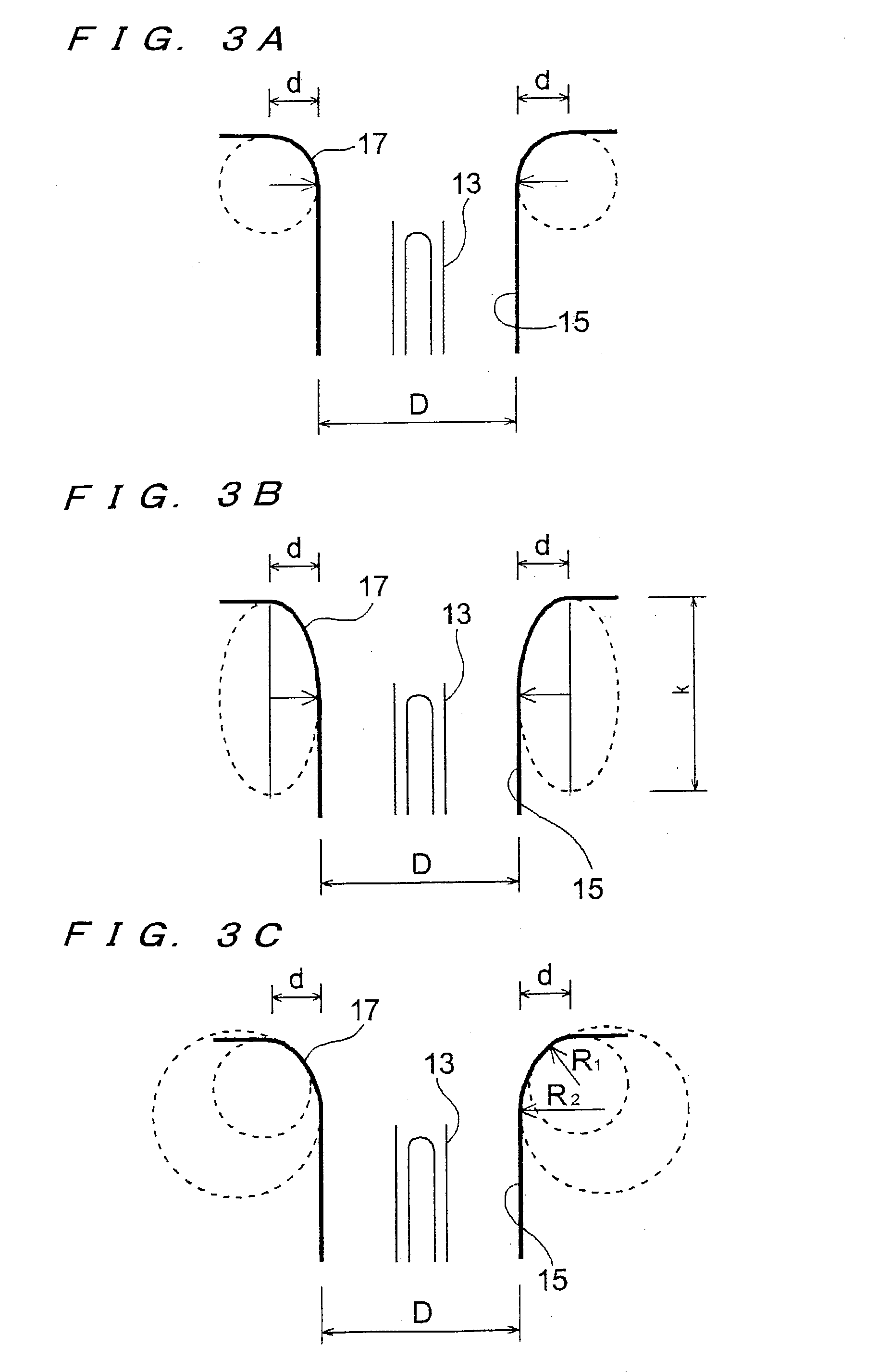
[0059] Diameter of the inner wall surface irradiated with ultraviolet rays: 200 mm

[0060] Bell-mouthed surface: defined by an arc which is one-quarter of a true circle having a diameter of d=30 mm

[0061] Flow rate of the liquid: 50 to 250 l / minute

[0062] Operating time: 24 hours

[0063] Speed of the swirling flow in the liquid retention tank: 20 to 100 cm / second

[0064] As a result, the thin-film liquid layer on the inner wall surface of the cylinder was formed stably under the conditions of the flow rates up to 250 l / ...


PUM


Abstract

An electromagnetic wave applying apparatus according to the present invention has an electromagnetic wave source (13) such as an ultraviolet lamp or the like, a cylinder (15) surrounding the electromagnetic wave source, a liquid retention tank (16) disposed around the cylinder, and an inlet portion (17) for introducing a liquid overflow from the liquid retention tank as a thin film flowing down an inner wall surface of the cylinder, which is irradiated with an electromagnetic wave from the ultraviolet lamp (11). The electromagnetic wave applying apparatus also has swirling flow forming means for causing the liquid introduced from the inlet portion (17) onto the inner wall surface of the cylinder to flow as a swirling flow down the inner wall surface. The electromagnetic wave applying apparatus allows a large amount of liquid to be stably treated by the application of an electromagnetic wave without causing the electromagnetic wave source such as an ultraviolet lamp or the like to be contaminated.

Description

[0001] The present invention relates to an apparatus for and a method of applying an electromagnetic wave to a liquid, and more particularly to an apparatus for and a method of applying an electromagnetic wave such as ultraviolet rays or the like to various liquids including water being processed in wastewater treatment plants, industrial drains, water for various uses, sewage, purified water, drinking water, pure water, ultrapure water, etc.[0002] The application of electromagnetic waves such as ultraviolet rays or the like to liquids is widely used for the purposes of treating or sterilizing trace amounts of contaminants by way of excitation and / or dissociation of molecular bonds of organic substances or oxidizing agents. According to such a process, ultraviolet rays and an oxidizing agent such as ozone are used together to generate OH radicals, which decompose underwater contaminants by way of oxidization. The process does not produce secondary waste materials and is capable of d...

Claims


Application Information

Patent Timeline
IPC IPC(8): B01J19/12B01J19/24C02F1/32C02F1/38C02F1/72C02F1/78
CPCB01J19/123B01J19/125B01J19/127B01J19/128B01J19/129B01J19/247C02F2201/3223C02F1/38C02F1/722C02F1/725C02F1/78C02F2101/36C02F2103/06C02F1/325
Inventor NAKAGAWA, SOTATANAKA, TOSHIHIROKOSAKA, YASUSHIIMAI, MITSURU
Owner EBARA ENG SERVICE
Why Eureka
Try Eureka