Image forming method and image forming system
a technology of image forming and forming method, which is applied in the direction of dyeing process, drying, light and heating apparatus, etc., can solve the problems of inability to achieve the effect of forming, inability to transfer, and inability to print inkjet,
- Summary
- Abstract
- Description
- Claims
- Application Information
AI Technical Summary
Problems solved by technology
Method used
Image
Examples
example 1
[0037] Nassenger KS-1600 Type II (manufactured by Konica Corp.) was employed as an ink-jet printer. The ink specifically used for Nassenger containing 5% or more glycerine (produced by Konica Corp.) was used. Used inks were 8 colors, including dispersed dyes of yellow, magenta, cyan and black, and light-colored inks thereof. Polyester China crepe was used as textile media, which is dipped in a solution having the following composition as a pretreatment, mangled and then dried.
1 gum sizing agent 1% cationic polymer 2% fluorinated water repellent agent 1% water 96%
[0038] The pretreated textile was fed to an ink-jet printer and a 1200 mm wide, 500 mm long printed portion of black solid image at a total ink coverage of 50 g / m.sup.2 and a 500 mm long non-printed portion were alternated for 40 m, wound up simultaneously with Nassenger KS-1600 Type II (manufactured by Konica Corp.) together with blank newspaper as an inserting medium, and thus the printed textile roll was prepared.
[0039] D...
example 2
[0044] A heater was provided around the chamber and a support stand was provided for the printed textile roll in drying apparatus "A", to prepare drying apparatus "B".
[0045] Another printed textile roll was prepared in the same way as in Example 1, and placed into drying apparatus "B". The heater was adjusted to a temperature of 60.degree. C. with bringing a thermo couple into contacted with the printed textile roll and the roll was allowed to stand for about 20 min.
[0046] Next, the chamber was evacuated for 60 min by adjusting the orifice valve to make the degree of vacuum 0.1 Pa.
[0047] After removing the inserting medium, the textile was folded and a load of 5 Kg was applied thereto, and the roll was subjected to a color forming treatment by a continuous high temperature and high humidity steamer of 170.degree. C., and thus roll sample B was obtained. In addition, water of less than 10.degree. C. instead of liquid nitrogen was used in the trapping vessel.
example 3
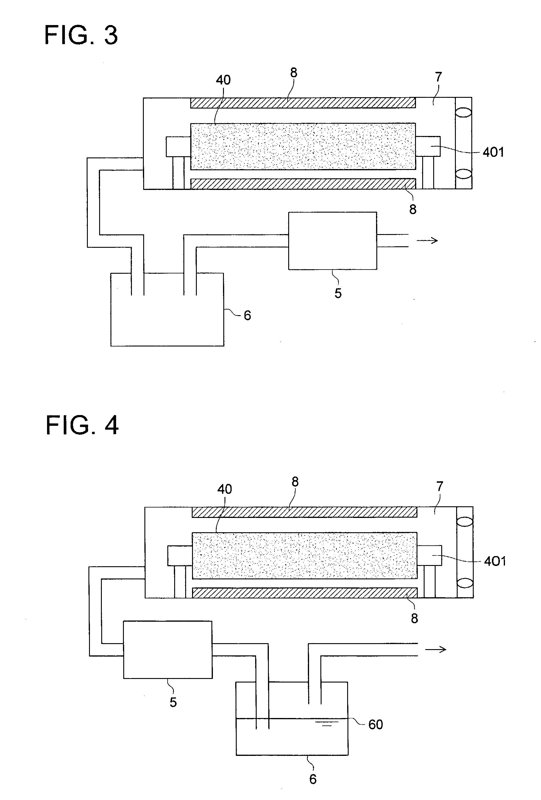
[0048] The evacuator in drying apparatus "A" was replaced with a diaphragm type dry vacuum pump, and a chamber, an evacuator and a trapping vessel were connected in the above order. An orifice valve was installed between the chamber and the evacuator, and thus drying apparatus "C" was prepared.
[0049] The printed textile roll was prepared in the same way as in Example 1, and placed into drying apparatus "C", after which the chamber was evacuated for about 180 min so that the degree of vacuum was to be 100 Pa.
[0050] An exhaust pipe was placed into water as shown in FIG. 4 so as to dissolve a solvent into water.
[0051] After that, the inserting medium was removed and the textile was folded and a load of 5 Kg was applied thereto, and the roll was subjected to a color forming treatment by a continuous high temperature and high humidity steamer of 170.degree. C., and thus roll sample C was obtained.
PUM
| Property | Measurement | Unit |
|---|---|---|
| boiling point | aaaaa | aaaaa |
| pressure | aaaaa | aaaaa |
| pressure | aaaaa | aaaaa |
Abstract
Description
Claims
Application Information
 - R&D
- Intellectual Property
- Life Sciences
- Materials
- Tech Scout
- Unparalleled Data Quality
- Higher Quality Content
- 60% Fewer Hallucinations
Browse by: Latest US Patents, China's latest patents, Technical Efficacy Thesaurus, Application Domain, Technology Topic, Popular Technical Reports.
© 2025 PatSnap. All rights reserved.Legal|Privacy policy|Modern Slavery Act Transparency Statement|Sitemap|About US| Contact US: help@patsnap.com


