
Method, system, and program for error handling in a dual adaptor system where one adaptor is a master

a dual adaptor system and error handling technology, applied in loop networks, fault response, instruments, etc., can solve problems such as large inability to meet the requirements of high availability systems, and general unacceptable delays in i/o processing, so as to avoid any delays in altering the master configuration, reduce any delays, and avoid any master switching delays

Inactive Publication Date: 2003-05-29
IBM CORP
View PDF5 Cites 34 Cited by
  • Summary
  • Abstract
  • Description
  • Claims
  • Application Information

AI Technical Summary

Benefits of technology

[0015] The described implementations provide improved error handling techniques when detecting a problem with the ability of another adaptor to communicate to the system in which the adaptor is housed. The described error handling techniques reduce delays in I / O processing when detecting errors in the ability of other adaptors to communicate to the system in which they are housed.
[0031] The logic of FIG. 3 thus provides a greater degree of intelligent monitoring in cases where there is a problem in the system including one adaptor that will eventually result in a reset after a period of time that is longer than an acceptable I / O delay time given the availability requirements of the system. With the described implementations, unacceptable I / O delays are not experienced while waiting for the system or I / O bay including the other adaptor to reset. The described implementations are particularly suited for situations where the detected problem between the target adaptor 4b and system 2b including the adaptor is not likely to prevent I / O requests at other adaptors from completing. The logic of FIG. 3 would allow one adaptor to continue processing I / O requests and wait for the detected adaptor to internally reset without having to interrupt I / O processing.
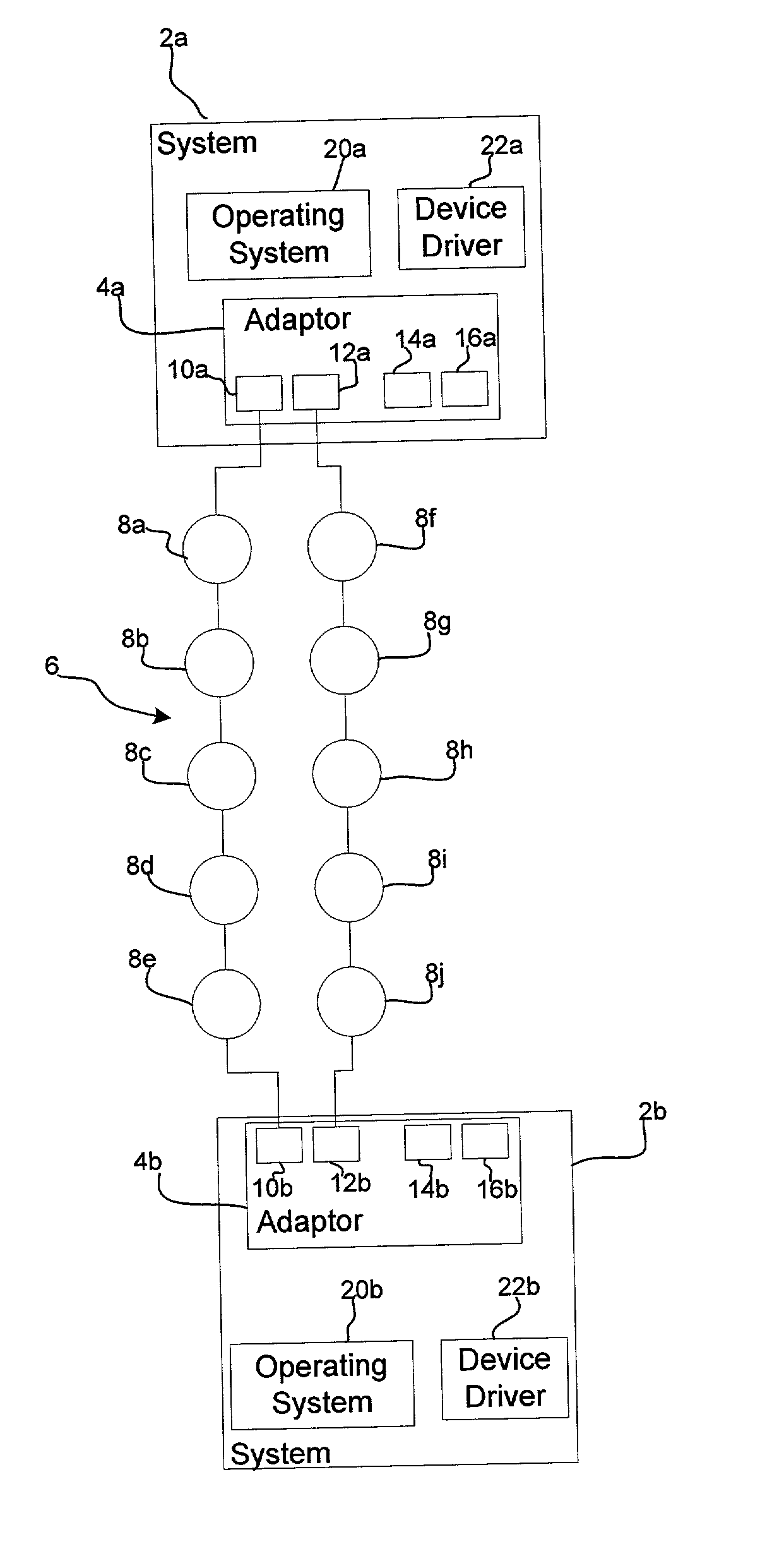
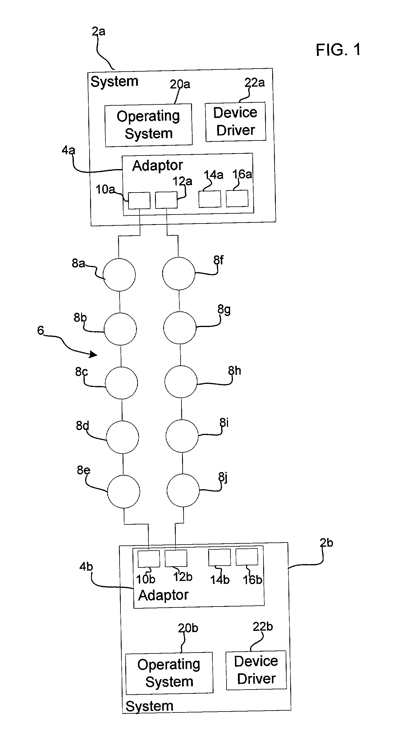
[0032] FIGS. 4a and 4b illustrate logic implemented in the device drivers 22a and 22b to account for the fact that the adaptor 4a, 4b in the system where the communication error is detected includes the master adaptor for the loop 6. The logic of FIGS. 4a and 4b provides for a modification of the logic of FIG. 3 to reduce any delays associated with switching the master if the master adaptor is in the target adaptor that will be subject to reset. The steps at block 200, 202, 204, 205, 206, 208, 210, 212, and 214 are identical to the steps performed at blocks 100, 102, 104, 105, 106, 108, 110, 112, and 114 in FIG. 3. The logic diverges in FIGS. 4a and 4b to provide for switching the master if necessary to avoid any delays in altering the master configuration. Upon receiving notification that an I / O timer expired (at block 214), the device driver 22a performs the steps at blocks 216, 218, and 220 (which are identical to steps 116, 118, and 120 in FIG. 3) to issue the command to do the reset of the system / I / O bay where the error was detected. As discussed, the reset may comprise a reset of the adaptor 4b only, or in additional implementations a power cycle command for the system 2 or power boundary including the target adaptor 4b.
[0033] Upon detecting the error at block 200, and concurrently with starting the window timeout timer (at block 202) and monitoring for received I / O requests (at block 206), an additional process is initiated at block 230 (FIGS. 4a and 4b). With respect to FIG. 4b, if (at block 230) the adaptor 4b (housed in the system 2b where the error was detected) is the master, then a timer is started (at block 232) for a master switch timeout period. The master switch timeout period is a timeout period selected to change the master in a manner that avoids any master switching delays should the target adaptor 4b in the system where the error was detected be reset. In certain implementations, the master switch timeout period is set to a value less than the window timeout timer and the I / O delay timeout to ensure that the master is switched before the reset occurs following the I / O timer or window timer expiring, so that the resetting process will not be further delayed by having to wait for a switch of the master to another adaptor when the target adaptor 4b goes offline during the reset period. In this way, any I / O processing delays due to a master switch operation are avoided.
[0036] The logic of FIGS. 4a and 4b provides additional checking over the logic of FIG. 3 to avoid any delays incurred when changing the mastership of the loop 6 from the target adaptor 4b being reset to another adaptor on the loop 6. In such case, the described implementations provide a master switch timeout period to ensure that the mastership of the loop 6 is switched before the target adaptor 4b is subject to a reset command to avoid any I / O delays related to switching the mastership on the loop 6.Additional Implementation Details

Problems solved by technology

In such instances, the system detecting the problem will delay I / O processing for a timeout period that corresponds to the time required for the other system including the adaptor to initiate an error recovery procedure.
In storage systems requiring high availability, such as storage systems for critical uses, any delays in I / O processing are generally unacceptable.
Thus, extensive delays in I / O processing, such as a delay resulting from the lengthy timeout period for the error recovery process at the detected system, would be unacceptable in a high availability system.
In addition to delays that may result from having to wait for the system housing the other adaptor to reset, additional delays may be incurred when a master adaptor is subject to the reset.
However, if the master is reset, then the I / O delay may double to 8 to 16 seconds due to the additional time needed to switch the master to another adaptor.

Method used


Image

  • Method, system, and program for error handling in a dual adaptor system where one adaptor is a master
  • Method, system, and program for error handling in a dual adaptor system where one adaptor is a master
  • Method, system, and program for error handling in a dual adaptor system where one adaptor is a master

Examples


Embodiment Construction

[0011] Provided is a method, system, and program for processing Input / Output (I / O) requests to a storage network including at least one storage device and at least two adaptors, wherein each adaptor is capable of communicating I / O requests to the at least one storage device. An error is detected in a system including a first adaptor, wherein the first adaptor is capable of communicating on the network after the error is detected. In response to detecting the error, a master switch timer is started that is less than a system timeout period if the first adaptor is the master. An error recovery procedure in the system including the first adaptor would be initiated after the system timeout period has expired. An operation is initiated to designate another adaptor in the storage network as the master if the first adaptor is the master in response to detecting an expiration of the master switch timer.

[0012] In further implementations, a reset request is sent to the first adaptor after the...


PUM


Abstract

Provided is a method, system, and program for processing Input / Output (I / O) requests to a storage network including at least one storage device and at least two adaptors, wherein each adaptor is capable of communicating I / O requests to the at least one storage device. An error is detected in a system including a first adaptor, wherein the first adaptor is capable of communicating on the network after the error is detected. In response to detecting the error, a master switch timer is started that is less than a system timeout period if the first adaptor is the master. An error recovery procedure in the system including the first adaptor would be initiated after the system timeout period has expired. An operation is initiated to designate another adaptor in the storage network as the master if the first adaptor is the master in response to detecting an expiration of the master switch timer.

Description

[0001] This application is related to the copending and commonly assigned U.S. patent application Ser. No. ______ entitled "Method, System, and Program for Error Handling in a Dual Adaptor System" having attorney docket no. TUC920010103US1, which patent application was filed on the same date herewith and is incorporated herein by reference in its entirety.[0002] 1. Field of the Invention[0003] The present invention relates to a system, method, and program for error handling in a dual adaptor system.[0004] 2. Description of the Related Art[0005] In a storage loop architecture, such as the Serial Storage Architecture (SSA), a plurality of disks are interconnected to one or more adaptors so that either of the adaptors can access the one or more loops of interconnected disks. An adaptor may include two or more ports to allow connection to one or more loops. For each loop on which the adaptor communicates, one adaptor port connects to a first disk in the loop and the other port connects ...

Claims


Application Information

Patent Timeline
Patent Type & Authority Applications(United States)
IPC IPC(8): G06F11/00G06F11/07
CPCG06F11/0727G06F11/0745H04L12/42G06F11/0793G06F11/2089G06F11/0757
Inventor FAIRHURST, MATTHEW JOHNJONES, MICHAEL JOHNLEGVOLD, VERNON J.VAGELINE, MICHAEL P.
Owner IBM CORP
Learn More