
Battery pack and cordless power tool using the same as power source

Inactive Publication Date: 2003-05-22
HITACHI KOKI CO LTD
View PDF6 Cites 1311 Cited by
  • Summary
  • Abstract
  • Description
  • Claims
  • Application Information

AI Technical Summary

Benefits of technology

[0018] A battery temperature detector may further be provided for detecting a temperature of the battery. The switching unit is rendered OFF when the temperature of the battery detected by the battery temperature detector exceeds a predetermined temperature. When the battery is continuously discharged, Joule heat is generated in proportion to the duration of discharge so that the temperature of the battery increases. If the battery temperature becomes extremely high, then the electrolyte in the battery can boil. Even if the battery temperature is not high enough to boil the electrolyte, the life of the battery can be shortened by continuous use at high temperature. Therefore, there is a need to manage the temperature of the battery. With the battery temperature detector, it is judged whether or not the battery temperature is at an abnormally high temperature greater than a predetermined temperature. When the battery temperature is judged to be abnormally high, then further discharge of the battery, that is further use of the power tool, is prohibited.

Problems solved by technology

This can shorten the cycle life of the battery pack.
That is, lower capacity cells tend to overcharge and over-discharge when normal capacity cells contained in the same battery pack are properly charged and discharged, which shortens the life of the lower capacity cells compared to the other cells.
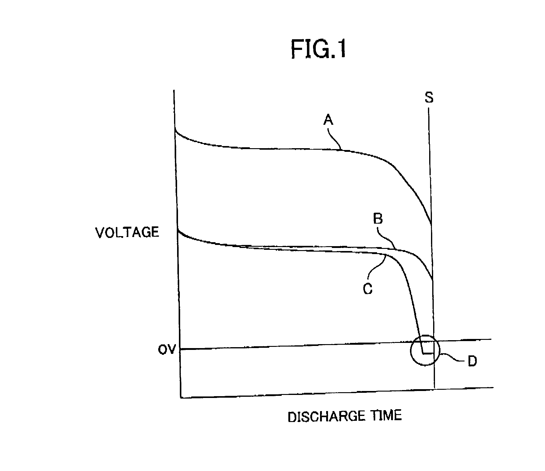
It is assumed that the operator turns off the power tool at time S because the voltage of the battery is judged to be no longer sufficient to drive the motor of the power tool.
Typically, power tools are not provided with a function for preventing over-discharge of the battery.
Therefore, in the case of using the battery pack for a power tool, rotation of the power tool's motor will slow down.
If the battery temperature becomes extremely high, then the electrolyte in the battery can boil.

Method used


Image

  • Battery pack and cordless power tool using the same as power source
  • Battery pack and cordless power tool using the same as power source
  • Battery pack and cordless power tool using the same as power source

Examples


Embodiment Construction

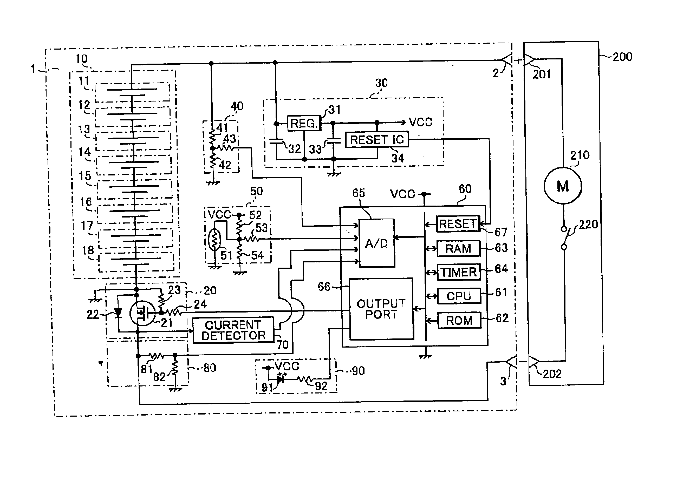
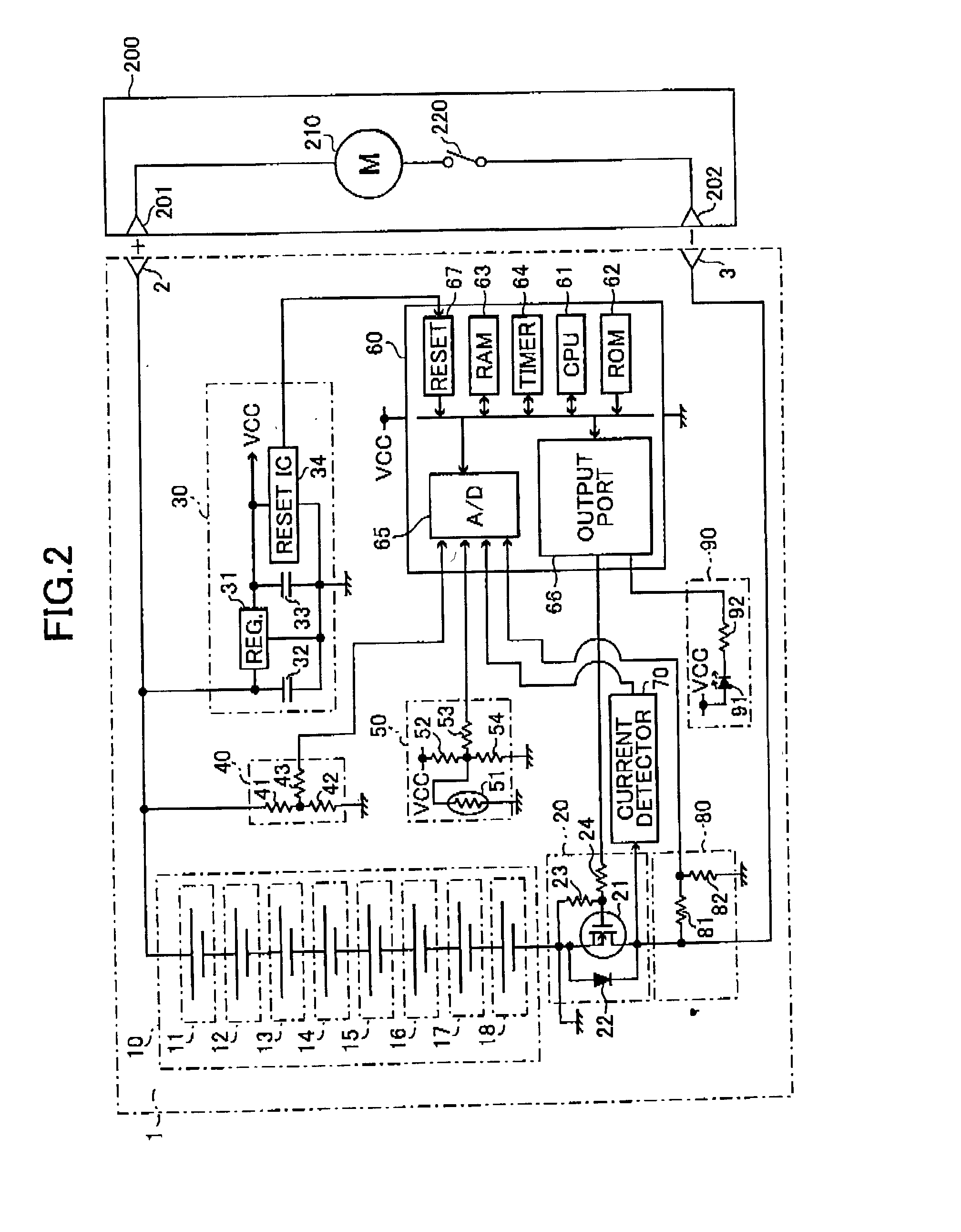
[0024] Next, a battery pack 1 according to an embodiment of the present invention will be described with reference to FIGS. 2 and 3. FIG. 2 is a circuit diagram showing the battery pack 1 connected to a power tool 200. The battery pack 1 has a positive terminal 2 and a negative terminal 3. The positive terminal 2 is connected to a positive terminal 201 of the power tool 200 and the negative terminal 3 is connected to a negative terminal 202 of the power tool 200. A DC motor 210 and a switch 220 are connected in series between the positive terminal 201 and the negative terminal 202 of the power tool 200.

[0025] The battery pack 1 includes a battery 10, a switching portion 20, a constant voltage power source 30, a battery voltage detector 40, a battery temperature detector 50, a microcomputer 60, a current detector 70, a trigger detector 80, and a display 90.

[0026] The battery 10 includes cells 11-18 that are connected in series by connection plates. The cells of the battery 10 are sup...


PUM


Abstract

To prevent a battery from being over-discharged and to thus improve a cycle life of the battery, a microcomputer electrically interrupts connection between the battery and a cordless power tool to compulsorily stop driving the tool when the battery voltage has become equal to or fallen below a first predetermined value. Also, to enable an operator to know that the battery is in a near over-discharge condition, the microcomputer performs a switching control of a load current when the battery voltage is above the first predetermined voltage but has become equal to or falls below the second predetermined voltage. As a result, the rotation of the motor of the tool goes abruptly slow down or the motor rotates in an irregular fashion, whereby the operator recognizes that the battery is in a charge-need condition.

Description

[0001] 1. Field of the Invention[0002] The present invention relates to a battery pack including a secondary battery used as the power source for a cordless power tool.[0003] 2. Description of the Related Art[0004] Recently, secondary batteries, such as nickel-cadmium batteries, nickel-hydrogen batteries, and lithium-ion batteries, have increased their capacity and greatly improved charge / discharge performance when charged and discharged with large current. These high-performance secondary batteries are used as the power source of high-load machines, such as cordless power tools (referred to as simply "power tools" hereinafter). Secondary batteries used in power tools are normally in the form of a battery pack that includes a battery made from battery cells connected in series by, for example, a connection plate. The battery pack is mounted in the power tool to drive a motor for tightening screws or for performing other operations.[0005] However, when a power tool is driven using a ...

Claims


Application Information

Patent Timeline
IPC IPC(8): H01M6/50H01M10/44H01M10/48H02J7/00
CPCH01M6/5044H01M10/44H02J2007/004H01M2200/10H02J7/0031H01M10/482H02J7/00306Y02E60/10
Inventor TAKANO, NOBUHIROHARADA, HIDEKAZU
Owner HITACHI KOKI CO LTD
Learn More