
Systems and methods for reducing position errors in image correlation systems during intra-reference-image displacements

a technology of image correlation system and position error, applied in image data processing, instruments, image analysis, etc., can solve problems such as systematic displacement errors within sub-pixels, system and method disclosure, and inability to compensate position errors in image correlation system

Inactive Publication Date: 2003-05-15
MITUTOYO CORP
View PDF9 Cites 41 Cited by
  • Summary
  • Abstract
  • Description
  • Claims
  • Application Information

AI Technical Summary

Benefits of technology

[0029] In various other exemplary embodiments of the correlation systems and methods according to this invention, the systems and methods are particularly well-suited to reducing accumulated errors in an image correlation with speckle-image type readheads at high speed with high accuracy.

Problems solved by technology

In conventional image correlation systems and high-accuracy laboratory systems where sub-pixel resolution is needed, systematic displacement errors within a sub-pixel are introduced when determining a displacement to a sub-pixel resolution between a reference image and a second image.
However, the systems and methods disclosed in the 636 application do not compensate position errors in image correlation systems that are due to uncollimated light sources, or optical distortions, or both.
In addition to the systematic displacement errors, the inventors have determined that image correlation systems and high-accuracy laboratory systems where sub-pixel resolution is needed suffer from position errors that arise due to uncollimated light sources, or optical distortions, or both.
For example, the systems and methods disclosed in the 671 application do not compensate position errors in image correlation systems that are due to uncollimated light sources, or optical distortions, or both.
Similarly, the systems and methods disclosed in the 636 application do not compensate position errors in image correlation systems that are due to uncollimated light sources, or optical distortions, or both.
That is, intra-reference-image position errors are errors that occur over a range of displacements that do not require the reference image to be changed.
The inventors have found that such intra-reference-image errors detrimentally affect the accuracy of image correlation systems when the position of the second image is displaced by more than a few pixels from the reference image position.
Consequently, unless reference image positions are switched every few pixels, the accuracy of image correlation systems suffers due to these position errors.
On the other hand, frequently switching reference image positions to avoid such position errors may detrimentally affect system memory requirements and the speed with which the measurements can be made.
This can also increase the errors that accumulate when switching reference images, as discussed in the 636 application.
In both conventional image correlation devices and laboratory systems that use image correlation in high-accuracy positioning and the like, the practical problems from position errors that occur due to uncollimated light sources and optical distortions have not been adequately considered.
In particular, these conventional devices and high-accuracy laboratory systems and the like have given insufficient consideration to reducing or correcting for the position errors that arise due to uncollimated light sources and / or optical distortions.
That is, these conventional devices and high-accuracy laboratory systems and the like have given insufficient consideration to the position errors that might occur due to uncollimated light sources and / or optical distortions when the displacement exceeds a few pixel pitches.
These position errors, and other such intra-reference-image position errors, are characteristic of a particular system design and / or construction.
Thus, for a particular system design and / or construction, such errors may be characterized in relation to displacements relative to an unspecified or arbitrary reference image position.

Method used


Image

  • Systems and methods for reducing position errors in image correlation systems during intra-reference-image displacements
  • Systems and methods for reducing position errors in image correlation systems during intra-reference-image displacements
  • Systems and methods for reducing position errors in image correlation systems during intra-reference-image displacements

Examples


Embodiment Construction

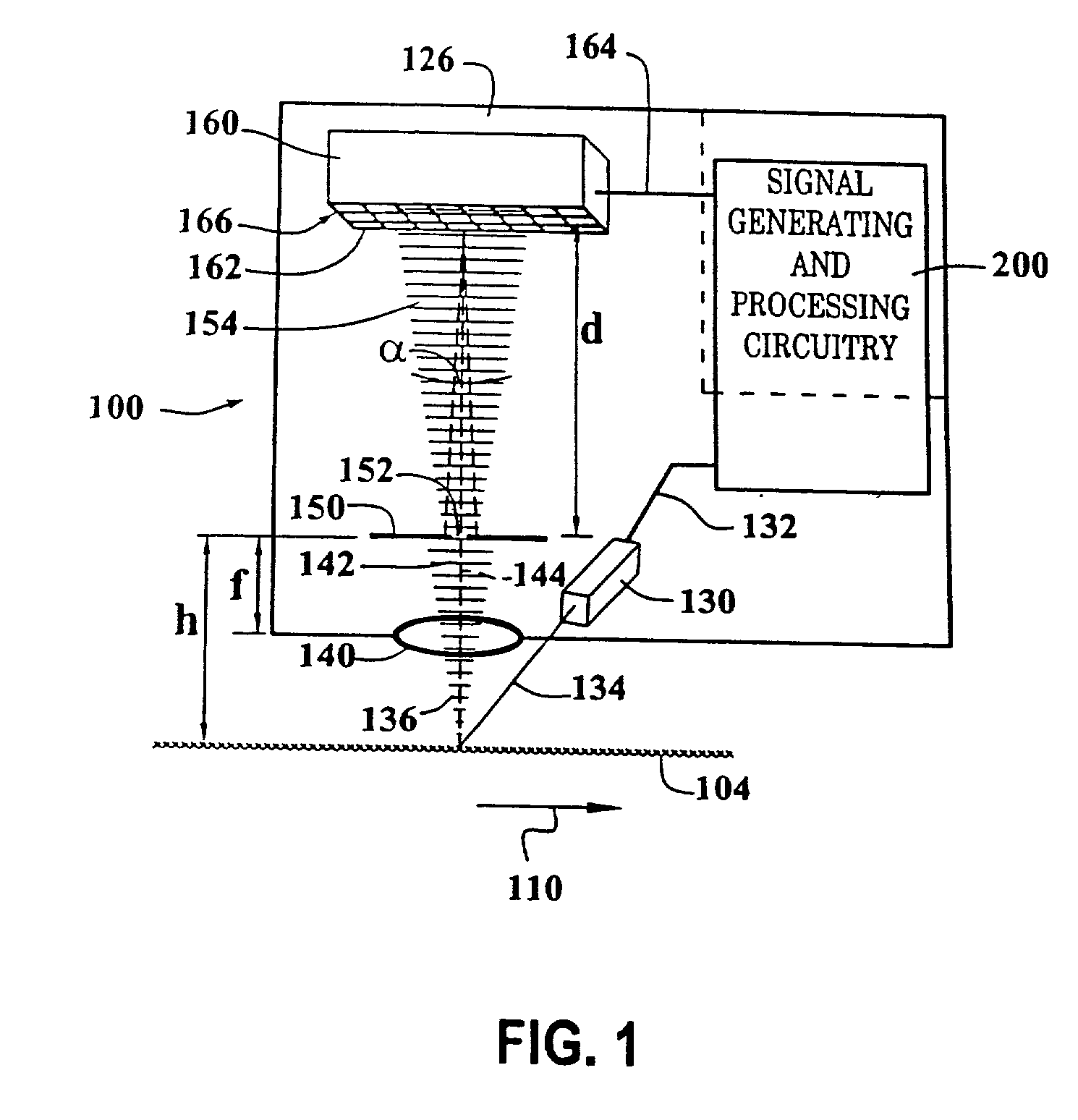
[0047] FIG. 1 is a block diagram of a speckle-image-based optical position transducer 100. The speckle-image-based optical position transducer 100, as well as various suitable mechanical and optical configurations, image correlation methods, and associated signal processing circuitry, are described in greater detail in co-pending U.S. application Ser. No. 09 / 584,264, expressly incorporated herein by reference in its entirety and for all purposes.

[0048] The speckle-image-based optical position transducer 100 shown in FIG. 1 includes a readhead 126, signal generating and processing circuitry 200 and an optically rough surface 104. In FIG. 1, the components of the readhead 126, and their relation to the optically rough surface 104, are shown schematically in a layout that generally corresponds to an exemplary physical configuration, as further described below.

[0049] In particular, the optically diffusing, or optically rough, surface 104 is positioned adjacent to an illuminating and rec...


PUM


Abstract

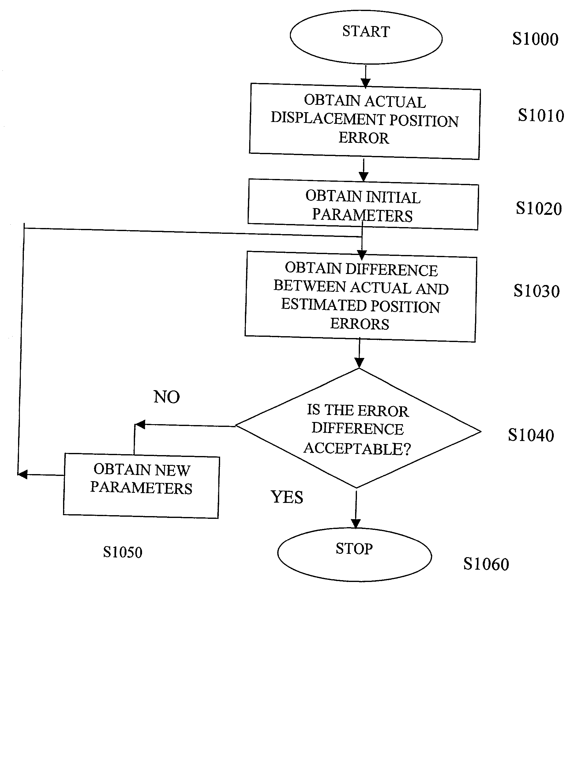
A position error correcting, or reducing, method and system used in an image-correlation system which obtains an error function generally reflecting an error occurring over a nominal reference image update length and an error occurring at a first frequency and various other system errors. The error can be compared to a first reference to fit the position error. In various embodiments, parameters of an error function can be varied in fitting the error function to the first reference. The obtained error function can then be used to determine the position error and render more accurate the image correlation system. In one exemplary implementation, the first frequency is related to a pixel pitch and the nominal reference image update length related to the distance between reference image changes is the maximum usable reference image update length.

Description

[0001] 1. Field of Invention[0002] This invention is directed to image correlation systems.[0003] 2. Description of Related Art[0004] Various known devices use images acquired by a sensor array, and correlation between the images acquired by the sensor array, to determine deformations and / or displacements. For example, one class of such devices is based on acquiring a speckle image generated by illuminating an optically rough surface with a light source. Generally, the light source is a coherent light source, such as a laser-generating light source. Such laser-generating light sources include a laser, a laser diode, and the like. After the optically rough surface is illuminated by the light source, the light scattered from the optically rough surface is imaged onto an optical sensor. The optical sensor can be a charge-couple device (CCD), or a semi-conductor image sensor array, such as a CMOS image sensor array or the like.[0005] Prior to displacing or deforming the optically rough ...

Claims


Application Information

Patent Timeline
IPC IPC(8): G06T3/00G01B11/14G01B11/16G06T1/00G06T7/00
CPCG01B11/16G01B11/14
Inventor JONES, BENJAMIN K.NAHUM, MICHAEL
Owner MITUTOYO CORP
Learn More