
Tamdem crossbar switch with ultra low crosstalk

a crossbar switch and ultra-low crosstalk technology, applied in the direction of waveguide type devices, coupling devices, basic electric elements, etc., can solve the problems of reducing the signal to noise ratio (snr) of the switch, limiting lithography and yield, and the usual design cannot reach the goal of 1024.times.10.sup.24 port sizes

Inactive Publication Date: 2003-04-24
TERABURST NETWORKS
View PDF0 Cites 0 Cited by
  • Summary
  • Abstract
  • Description
  • Claims
  • Application Information

AI Technical Summary

Benefits of technology

[0077] The above-noted effect is most pronounced at high frequencies, e.g., 40 GHz, and for large switch sizes, e.g.,1K.times.1K. The implementation of the row and column transmission lines as stripline structures should exhibit smaller coupling than similar structures implemented as microstrip structures. However, stripline generally suffers from greater insertion loss due to the smaller traces, assuming a constant dielectric thickness. Hence stripline structures require a small pitch between lines (typically 4 mils) in order to reduce the length of the worst case signal path. Since insertion loss scales as dB / length, the smaller pitch greatly reduces insertion loss. However, it is more difficult to make chips with such a small pitch (with correspondingly smaller yields), and also the smaller pitch makes the chip more difficult to package, i.e., to design matched transitions from the chip to the board.

Problems solved by technology

Previously, it was thought that the only way to do this was to reduce the geometry and related coupling capacitance of each switch at each node of a crossbar switch array to near zero, but there are limits to lithography and yield.
As a result, the usual designs cannot approach the goal of 1024.times.10.sup.24 port sizes.
Since the inputs are pseudo random sources, this coupled crosstalk will appear as noise on the signal path, reducing the signal to noise ratio (SNR) of the switch, and leading to bit errors.
Forward Error Correction (FEC) techniques (see, for example, "FEC Performance Analysis Data Sheet S3062", Applied Micro Circuits Corporation, San Diego, Calif., Apr. 13, 2000; incorporated herein by reference) can sometimes suppress these bit errors, but this requires complex digital circuitry with large demands on system power consumption and real estate.

Method used


Image

  • Tamdem crossbar switch with ultra low crosstalk
  • Tamdem crossbar switch with ultra low crosstalk
  • Tamdem crossbar switch with ultra low crosstalk

Examples


Embodiment Construction

[0041] 1. Introduction

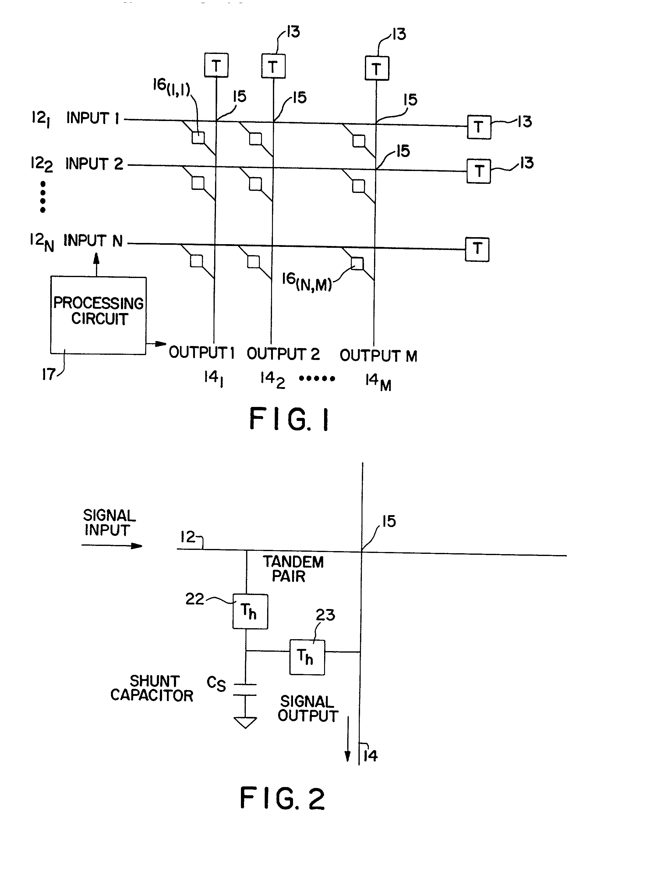
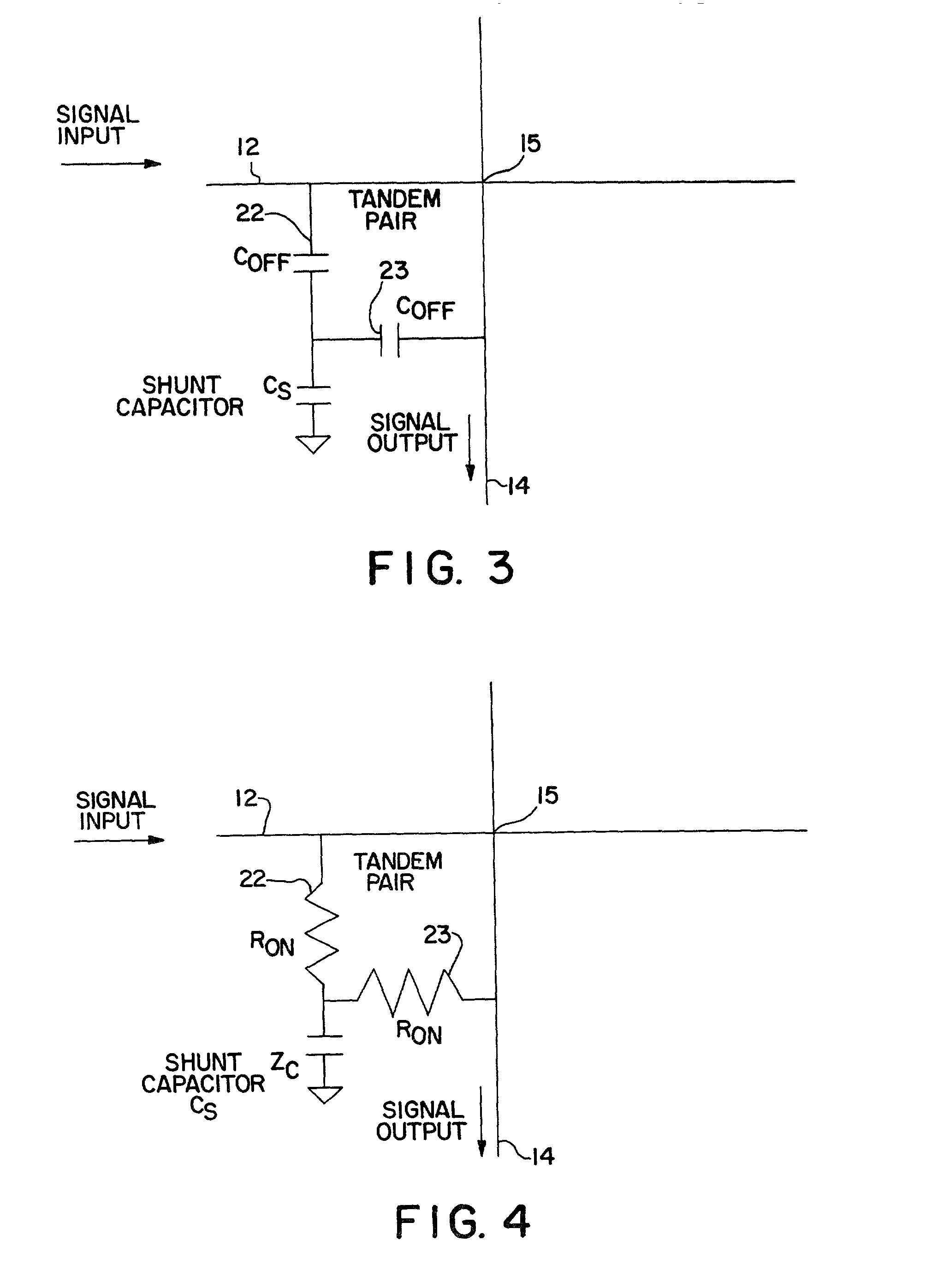
[0042] Briefly, the structure and function according to the present invention suppresses the spurious cross coupling .sigma. by using a tandem switch design for the crosspoint switch elements, as shown in FIG. 2. Instead of a simple ON-OFF switch (as used in the basic crossbar of FIG. 1), a tandem switch structure with a shunt capacitor is used to effectively short the crosstalk to ground.

[0043] 2. The Structure

[0044] FIG. 2 shows a crosspoint switch element according to a preferred embodiment of the present invention. For clarity, FIG. 2 depicts only a single crosspoint in a multi-crosspoint array. At each of the N.times.M cross-points 15 there is provided a tandem pair of thyristors 22, 23, and a shunt capacitor Cs. Depending upon the application, the shunt capacitor Cs may be shared among two or more thyristors. This is a new variety of N.times.M analog crossbar switch which uses a pair of semiconductor switches at each crosspoint to direct any of N incoming...


PUM


Abstract

Switching apparatus and method in an array having plural inputs and plural outputs crossing each other at a plurality of crosspoints. First and second tandem switches are disposed at each crosspoint, between a respective input and a respective output. A shunt capacitor is coupled to each first and second switch and to ground, to short crosstalk in the inputs and outputs. A method of making a semiconductor switch array is also provided.

Description

[0001] This application claims priority to Application No. 60 / 328,793 filed Oct. 15, 2001, incorporated herein by reference.[0002] 1. Field of the Invention[0003] The present invention relates to switching array method and apparatus capable of high signal speeds and dense integration, but with ultra low crosstalk. Preferably, the tandem switch array can switch up to 40 Gbs signals in a 1K.times.1K array, with 20 dB improvement in the SNR (signal-to-noise ratio).[0004] 2. Related Art[0005] Optical Cross Connects (OXCs) are used in a variety of applications whenever fiber optic lines are linked to each other in rings and networks, either for backbone cross country applications or for metropolitan applications. There is a need for an OXC telecommunication switch which has high bandwidth, high port count, wavelength conversion and low latency. An example of a technology that offers such features is described in a TeraBurst Networks publication by J. D. Levine, T. Myers, R. LaRue, L. Ram...

Claims


Application Information

Patent Timeline
Patent Type & Authority Applications(United States)
IPC IPC(8): H01P1/15
CPCH01P1/15
Inventor CLARKE, WILLIAM L.LEVINE, JULES D.FRESKE, STAN
Owner TERABURST NETWORKS
Learn More