
Method for operating an otto-cycle internal combustion engine with fuel injection on a cold start

Inactive Publication Date: 2003-04-24
ROBERT BOSCH GMBH
View PDF3 Cites 18 Cited by
  • Summary
  • Abstract
  • Description
  • Claims
  • Application Information

AI Technical Summary

Benefits of technology

0006] The method according to the present invention for operating a spark ignition internal combustion engine having fuel injection at a cold start is characterized by the following procedural steps:
0007] retarding the spark angle to a cold start value for at least the first combustion in at least one cylinder of the internal combustion engine during a cold start phase, while the fuel injected into the cylinder is brought to combustion;
0008] setting the spark angle to normal to end the cold start phase.
0009] Since the spark angle is retarded as far as possible for at least the first combustion in at least one cylinder, the fuel or fuel-air mixture injected into the combustion chamber is burned up in the corresponding ignition, and advantageously a very small torque is produced by this combustion.
0010] Consequently, the first combustion using retarded spark angle results in a very slight increase in rotational speed, so that there is also sufficient injection time available for the next immediately following injection to be able to inject sufficient fuel into the combustion chamber to ensure reliable combustion. At the same time it must also be kept in mind that already after the first combustion the combustion chamber is warmed up sufficiently so th

Problems solved by technology

This would disadvantageously cause combustion misfiring in the corresponding cylinders.
Because of the relatively great increase in rotational speed, there is no longer sufficient injection time available for the subsequent third and fourth injections to be able to inject an adequate quantity of fuel for combustion into the combustion chamber using the inlet valve (injection valve).
This causes unwanted combustion misfirings at the third and fourth injections during the cold start.
Providing such an additional cold start valve is relatively complicated and costly.

Method used


Image

  • Method for operating an otto-cycle internal combustion engine with fuel injection on a cold start
  • Method for operating an otto-cycle internal combustion engine with fuel injection on a cold start

Examples


Embodiment Construction

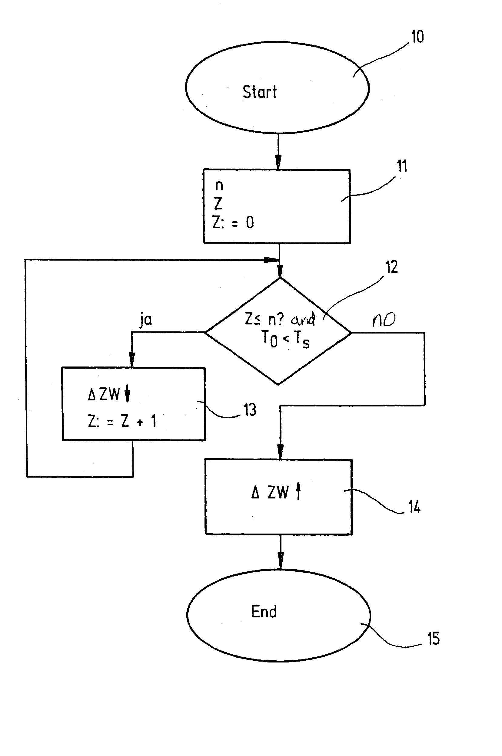
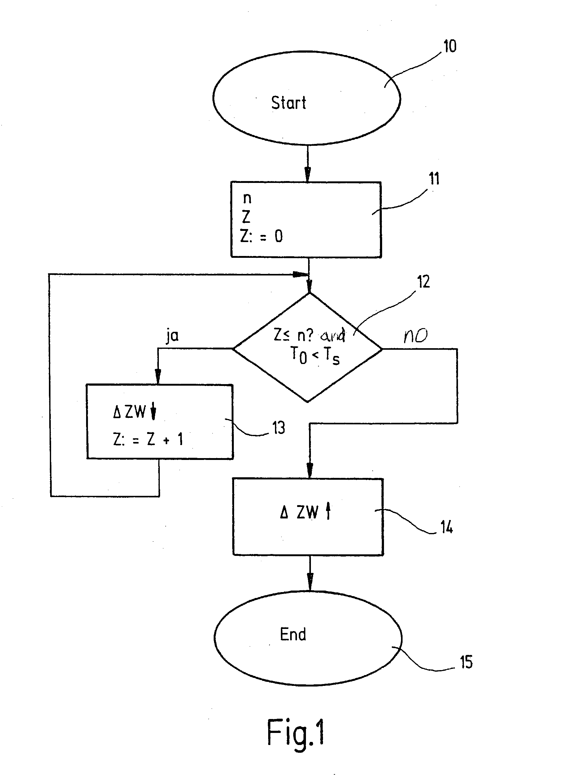
[0020] FIG. 1 shows a block diagram of a cold start spark angle adjustment, where the following definitions apply:

[0021] Block 10=start of the cold start spark angle adjustment;

[0022] Block 11=parameter acquisition with the parameters

[0023] n=freely applicable number where 1.ltoreq.n.ltoreq.number of cylinders,

[0024] z=number of ignitions;

[0025] Block 12=alternative polling;

[0026] Block 13=spark angle retardation .DELTA.ZW;

[0027] Block 14=spark angle normal setting .DELTA.ZW.Arrow-up bold.;

[0028] Block 15=end of the cold start spark angle adjustment.

[0029] When the internal combustion engine is started (Block 10), the cold start spark angle adjustment is started automatically; the freely applicable number designated as n (for example 1.ltoreq.n.ltoreq.number of cylinders in the engine) and the number of ignitions designated as z are defined as parameters (Block 11). These parameters n and z are determined by suitable means. Before the first ignition, z has the value 0. When the engi...


PUM


Abstract

A method is provided for operating a spark ignition internal combustion engine having fuel injection at a cold start. The method retards the spark angle to a cold start value at least for the first combustion in at least one cylinder of the internal combustion engine during a cold start phase, the fuel injected into the cylinder being brought to combustion, and the method sets the spark angle to normal, to end the cold start phase.

Description

[0001] The present invention relates to a method of operating a spark ignition internal combustion engine having fuel injection at a cold start according to the preamble of claim 1.BACKGROUND INFORMATION[0002] To start a spark ignition internal combustion engine having direct fuel injection, an initial pressure of around 4 bar, for example is, built up using an electrical fuel pump. The fuel injection itself is limited by an angle window whose beginning is normally defined by the moment of opening of an inlet valve and whose end is determined by the combustion chamber pressure that becomes established in the cylinder. Since the pressure in the combustion chamber rises during a compression phase and, starting at a certain piston position, exceeds the initial pressure built up by the electrical fuel pump, the fuel injection must be ended when the pressure in the combustion chamber exceeds a certain pressure threshold. Otherwise, air would incorrectly be blown from the combustion chamb...

Claims


Application Information

Patent Timeline
IPC IPC(8): F02B75/12F02D37/02F02D41/06F02P5/15
CPCF02B2075/125F02D37/02Y02T10/123F02P5/1506Y02T10/46F02D41/064Y02T10/12Y02T10/40
Inventor JOOS, KLAUSDAEUBEL, RALFGRASS, GERDWEISS, RUEDIGERBOCHUM, HANSJOERGSCHAUT, EDMUND
Owner ROBERT BOSCH GMBH
Learn More