Rotating stent delivery system for side branch access and protection and method of using same

Inactive Publication Date: 2003-03-20
GUMM DARREL C
View PDF89 Cites 234 Cited by
  • Summary
  • Abstract
  • Description
  • Claims
  • Application Information

AI Technical Summary

Benefits of technology

[0018] The present invention contemplates a new and improved apparatus and method that improves the orientation of a stent by providing a more exact placement of the stent relative to the side branch passage. This, in turn, leads to better protection of the side branch passage. The present invention has the potential for improvement in trackability of the stent delivery system.
[0020] The balloon is connected to the stent delivery system. In some embodiments, the balloon is attached both distally and proximally to rotate freely about the main hypotube. The rotating members rotate about the main hypotube and are limited longitudinally by first and second fixed members non-rotatably secured to the main hypotube. The balloon stent assembly rotates freely about the axis defined by the main hypotube and any radial movement is limited by the main hypotube. This construction allows the side branch guide wire to direct the stent assembly to rotate freely and passively to the proper circumferential orientation. Upon inflating the balloon, the fixed and rotated members secure the circumferential orientation of the stent delivery system. Thus, the side branch guide wire properly orients the stent delivery system in its correct position relative to the side branch.
[0024] Yet another benefit of this invention is the ability to properly place the stent delivery system longitudinally relative to the side branch.

Problems solved by technology

Although efforts have been made to use a stent at bifurcations, these sites have previously been inadequately treated by a stent.
However, problems are still encountered in orienting the stent relative to the side branch at the bifurcation of the main and branch passages.
These devices and methods of achieving proper angular orientation have not been shown to be effective in properly placing and positioning the stent.
As will be appreciated and understood by those skilled in the art, improper placement of the stent with respect to its rotational or circumferential orientation, or its longitudinal placement, could lead to obstruction of the side branch passage.
Commercially available devices do not maintain side branch access at the time of stent deployment.
This results in the potential for plaque shift and occlusion of the side branch passage.

Method used


Image

  • Rotating stent delivery system for side branch access and protection and method of using same
  • Rotating stent delivery system for side branch access and protection and method of using same
  • Rotating stent delivery system for side branch access and protection and method of using same

Examples


Embodiment Construction

is hereafter described with specific reference being made to the drawings.

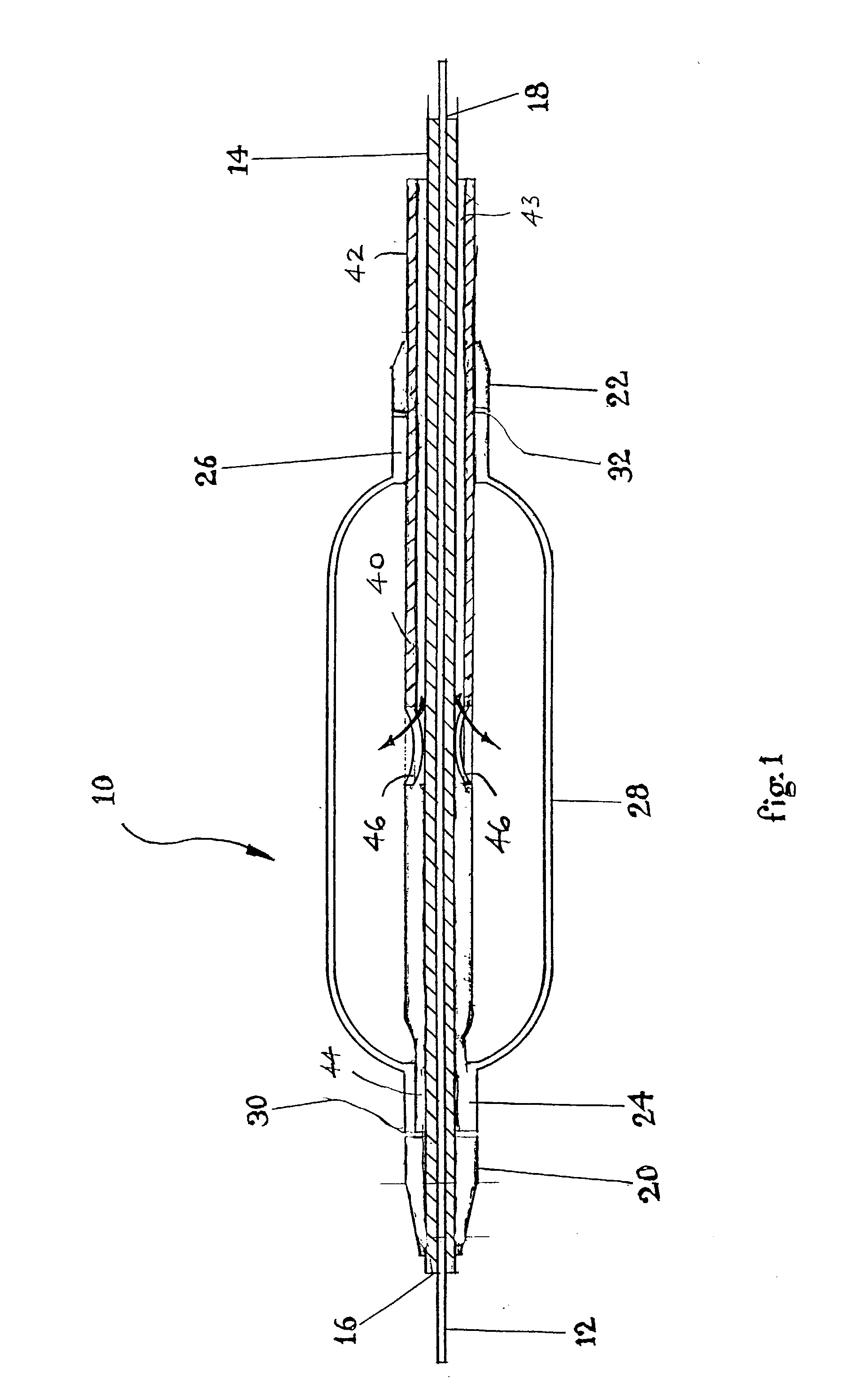
[0028] FIG. 1 is a cross-sectional side view of a rotating stent delivery catheter assembly for stenting an arterial bifurcation in its pre-deployment configuration, with the catheter balloon shown inflated.

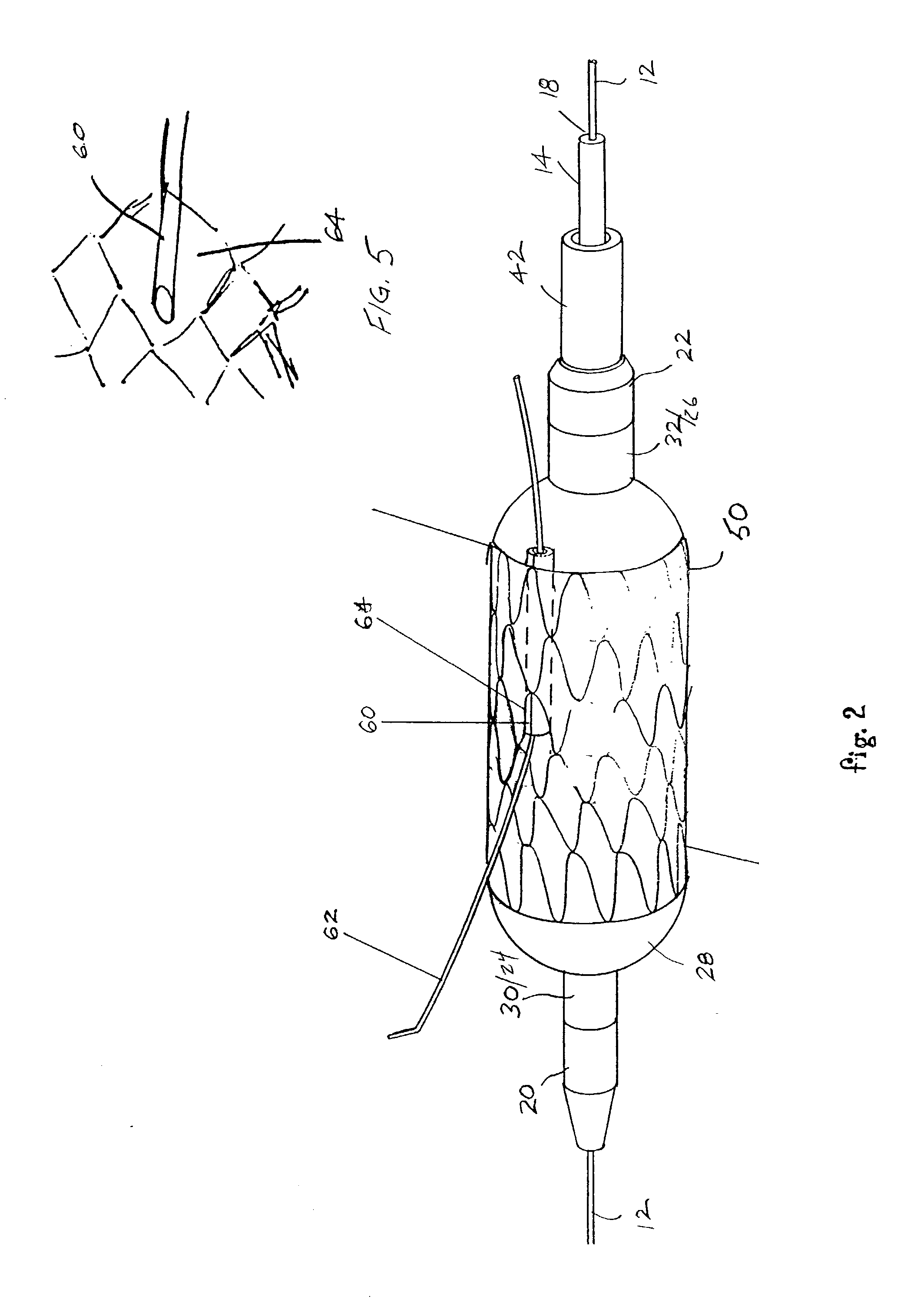
[0029] FIG. 2 is a perspective view of the stent delivery assembly of FIG. 1 shown with a stent disposed about the balloon.

[0030] FIG. 3 is a perspective view of the stent delivery catheter assembly of FIG. 1 as it would appear in the collapsed state prior to having a stent mounted on the balloon.

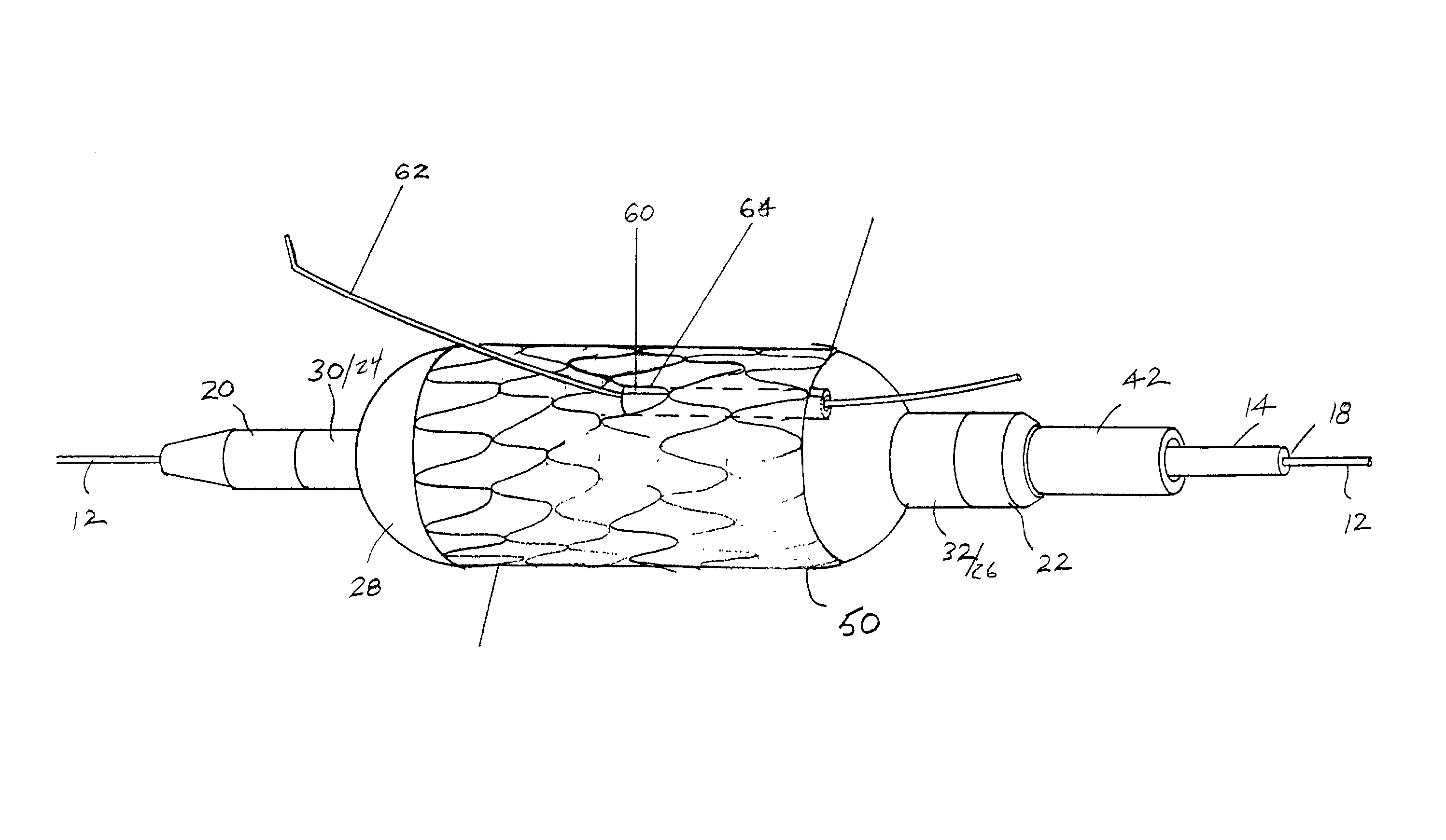
[0031] FIG. 4 is a perspective view of a stent delivery system with the balloon in an inflated state and the side branch hypotube in an open condition.

[0032] FIG. 5 is an enlarged view of the distal exit point of the side branch hypotube and the opening of the rotating stent delivery catheter assembly of FIG. 2.

[0033] FIG. 6 is a perspective view of a proximal shaft of an alternate stent delivery catheter assembly ...


PUM


Abstract

A catheter assembly and method of use comprises advancing a catheter having a rotatably mounted balloon relative to the primary guide wire to a vessel bifurcation along first and second guide wires.

Description

[0001] This application claims priority from U.S. provisional application No. 60 / 314,467, filed Aug. 23, 2001 the entire contents of which are incorporated herein by reference.[0002] Not Applicable[0003] 1. Field of the Invention[0004] At least one embodiment of the present invention is directed to the field of stents and stent delivery systems used to treat stenoses, and more particularly to stenoses at a bifurcation of a passage.[0005] 2. Description of the Related Art[0006] Stent systems are widely used in the treatment of stenoses. Intravascular stents are used in coronary, renal, and carotid arteries, for example, to maintain an open passage through the artery. In patients whose coronary heart disease consists of focal lesions, stents have proven effective. For example, where only a single coronary artery is clogged or where there are short blockages in more than a single artery, stents have been used with a great amount of success. An intravascular stent may be positioned in a...

Claims


Application Information

Patent Timeline
IPC IPC(8): A61F2/82
CPCA61F2/856A61F2/954A61F2/958A61F2002/821A61M2025/1056A61M2025/1045
Inventor GUMM, DARRELL C.
Owner GUMM DARREL C
Why Eureka
Try Eureka